
Welding is one of the most common techniques for joining metallic structures. It is an established solution that is used in sectors like construction, oil & gas industries, and shipbuilding, to name a few. Welding is a complex phenomenon that modifies the mechanical, chemical, and metallurgic properties of the joined components. In this blog post, we will focus on the different techniques for representing welds in finite element models and how stresses in welds can be evaluated to estimate the fatigue life.
Introduction to the Welding Process
Welding is a family of processes that create a permanent bond between two components by using high temperatures to melt the base material. Different energy sources, like combustion, electrical currents, electron beams, friction, or ultrasound can be used to achieve the temperatures needed in the welding process. Welding can be applied to metals or thermoplastics, but here, we will focus mostly on the welding of metals.
The welding process causes changes in the material that make the assessment of stresses in the welds a complex task. Some of these challenges include:
- Changes in the chemical composition
- The base metals and the filler alloy (if present) may change their chemical compositions during the process, as the direct mixing of the alloys in the weld pool or the high-temperature diffusion will alter the concentration of the alloy components.
- Changes in the metallurgic structures
- The high temperature during the welding process is likely to alter the microstructure of the regions adjacent to the weld pool. An alloy with the same chemical composition may present different microstructures due to the thermal profile followed during the cooling from high temperature. This change will also modify mechanical properties of the material like yield stress, ductility, or hardness. The Metal Processing Module can be used to analyze these effects in metallic alloys.
- Thermomechanical effects
- The difference in temperatures during the process and the thermal expansion of the alloys will create thermal stresses in the joint. Due to the reduction of yield stress of most alloys at high temperatures, this thermal stress is very likely to reach the yield stress of the base material or the fusion zone, inducing permanent warping of the joint and microcracks that will affect its fatigue life. The plastic strain generated during the process will induce residual stresses that will also affect the fatigue life of the joint.
- Geometric variations
- Due to the pulsating nature of some of the heat sources used or the variability of the process itself, geometric variations are likely to appear, causing a weld shape that differs from the ideal profile. This variation can induce additional stress concentrations.
Although it is possible to simulate the complete welding process in the COMSOL Multiphysics® software, as explained in this blog post on laser beam welding or as shown in this example of optimizing laser beam welding, most industrial applications call for a simplified assessment of the stresses in the weld to predict the fatigue life. These methods are described in standards and design codes and focus on the arc welding processes. Techniques like resistance welding or friction welding are not currently covered in these standards.
In this blog post, we will analyze some of these welding methods to assess the stress distribution in and around the welds and show how this can be modeled in COMSOL Multiphysics.
Welds and Fatigue
Fatigue is a process where materials subjected to cyclic loads well below the failure stress of the material under undamaged conditions will present cracks that eventually grow to cause failure of the component. The number of cycles to failure depends not only on the elastic properties of the material and the load but also on different factors like residual stresses, material fracture toughness, discontinuities, grain size, temperature, geometry, surface finish, or the presence of corrosion. As welds modify virtually all of these factors locally, it comes as no surprise that the prediction of the fatigue life in and around welds is a matter of much interest and research.
There are different methods used to predict the fatigue life based on the nature of the loading and the type of material subject to the cyclic load. For high numbers of cycles, most of these methods use S-N curves of the material. These curves give the relation between the level of stress and the number of cycles until a crack can be detected.
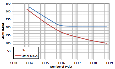
The graph shows the typical S-N curve of two families of alloys. Steel alloys usually have an endurance limit, below which fatigue failure will never appear. Other alloys may not have such an endurance limit, and any level of stress will eventually cause a failure.
As the figure above shows, a 10% variation in the stress can mean a difference of more than a factor of two in the number of cycles to failure (or even more in steel alloys). Thus, determining the stress at the weld with a good level of confidence is crucial for predicting the fatigue life of the weld.
Learn more about the fatigue methods and approaches available in the Fatigue Module, an add-on to the Structural Mechanics Module.
A Look at Weld Geometry
Welds are generally classified by the relative position of the components that are joined. In this example, we will analyze a fillet weld, which is a weld in which two components are joined at an angle. Fillet welds are a common solution used when joining pipes, perpendicular plates, or overlapping plates. A fillet weld is required to achieve complete fusion to the root and present a minimum dimension (in terms of throat thickness or leg length) through its length to be considered acceptable.
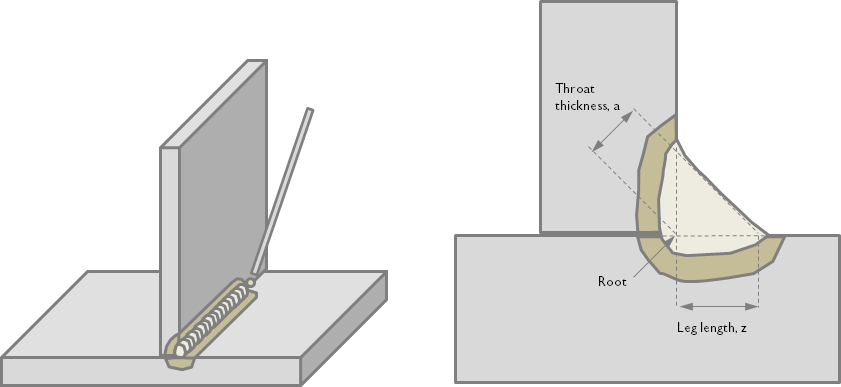
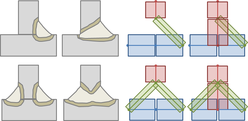
Schematic representation of the welding process of a fillet weld. The weld (light gray) presents a concave or convex surface, depending on the weld parameters and materials. The heat-affected zone or HAZ (khaki) has material properties that differ from the base material (dark gray).
As the quality of the weld is quite sensitive to the welding parameters (weld speed, preheating of the components, relative position of the weld tool, weld current, etc.), it is common to perform some inspection of the weld once it has been completed. Different techniques are available to assess the quality of the weld, ranging from visual inspection to ultrasonic inspection and dye penetrant inspection to fluorescent penetrant inspection.
Most welds produced in the field will not be subjected to enough inspection to guarantee complete penetration of the weld through the thickness of the joined plate. That is one of the reasons why it is quite common to use only the weld throat as a load path and assume that the base material does not contribute to the stiffness of the welded joint while performing a stress analysis of the weld.
Nominal Stress Method
Standards like the Eurocodes (EC) or the International Institute of Welding (IIW) allow designers to use the nominal stress method. This method, applicable only to certain materials and geometries, uses an equivalent stress or nominal stress computed at the weld and compares this stress to empirical S-N curves defined for each detail category.
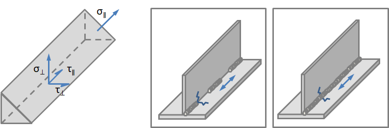
Stress components used for the computation of the equivalent stress and two categories for the weld.
This method has the advantage of its simplicity, but does present a series of limitations. It is not applicable to materials or constructive details not listed in the standard, and even for cases listed, it may be difficult to judge the class of the welded joint. Additionally, welded joints can develop fatigue cracks in areas different from those listed in the standard. Even with the shortcomings of the method, it is still the most commonly used due to its simplicity.
The IIW standard permits the use of finite element methods (FEM) to determine the nominal stress in cases where the loading is complex. In this case, a relatively simple and coarse model can be used to determine the nominal stress. In cases where the mesh is coarse, nodal forces rather than element stresses should be used in a section through the weld in order to avoid stress underestimation. Care must be taken to ensure that all stress concentration effects from the structural detail of the welded joint are excluded when calculating the modified (local) nominal stress.
The simplest FEM approach to determine the load distribution is to consider the welds as a continuity feature between welded components. This approach does not consider the flexibility of the weld throat and is therefore not valid when there is more than one weld that could act as a load path, or when determining the global stiffness of the structure is critical. Attention should be taken when considering the nodal forces measured using this approach, as some operations could be needed to translate them into stress in the welds.


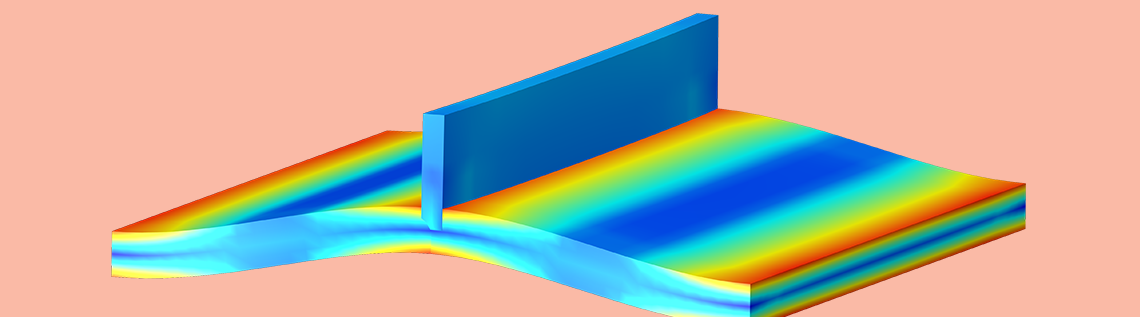
Example of a simplified weld analysis. The applied loads, mesh, and displacements are shown on the left. The 3D representation of the shell is shown in the center together with the von Mises stress. The nodal forces are shown on the right with the elements shrunk for clarity.
In the COMSOL Multiphysics context, “nodal forces” can be interpreted as reaction forces. Since reaction forces are only available where a constraint is present, an assembly joined by a continuity condition can be used.
A more accurate method of representing the welded joint is to actually model each individual throat with shells. This method requires the creation of surfaces in the midplane of the weld throat. The connection between the different plates will depend on the number of fillet welds and whether they present partial or total penetration. This method captures the flexibility of the throat and is therefore more suited for analyzing the load paths and stiffness of the global structure.
Four types of welds on the left and equivalent shell representations on the right. The thickness of the shell is represented as transparent boxes.
An example of a welded joint presenting two fillet welds of partial penetration is shown below. As seen in the figures below, this representation distributes the weld stress over a larger area, thus reducing the compliance and the stress around the weld. Another advantage of specifically representing the weld throat is that the nodal forces could be directly used to derive the nominal weld stress.


Example of a weld analysis where the throat of the weld is represented in the mesh. The applied loads, mesh, and displacements are shown on the left. The 3D representation of the shell is shown in the center together with the von Mises stress. The nodal forces are shown on the right with the elements shrunk for clarity. The color scales and magnitudes of the arrows are the same as in the previous images.
The nominal stress method is a relatively simple and inexpensive method to compute the fatigue life in a weld, and it is quite well adapted for using COMSOL Multiphysics to obtain the loads and stress distribution.
Effective Notch Stress Method
Another method to compute the fatigue life of a welded joint is to analyze the final geometry of the weld. This is called the effective notch stress method. This method requires that the structure is modeled as a solid, so the use of shells to approximate the behavior of the structure is precluded. The stress computed using this detailed model can be directly compared to a S-N curve, which is not specific for the type of joint. For the reasons described previously, welds present a high level of variability in their shape, so this method assumes an effective weld profile based on the throat thickness and a certain notch radius.


Model of a two-sided weld with complete penetration. The detail on the right shows how the peak stress is closely related to the assumed notch radius of 1 mm.
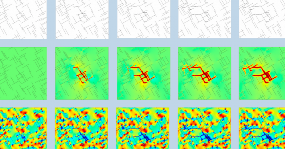
As seen in the previous figures, the stress distribution shows a very local peak, which would be impossible to capture unless the mesh is fine enough. The following figure shows the peak stress as a function of the minimum mesh size.
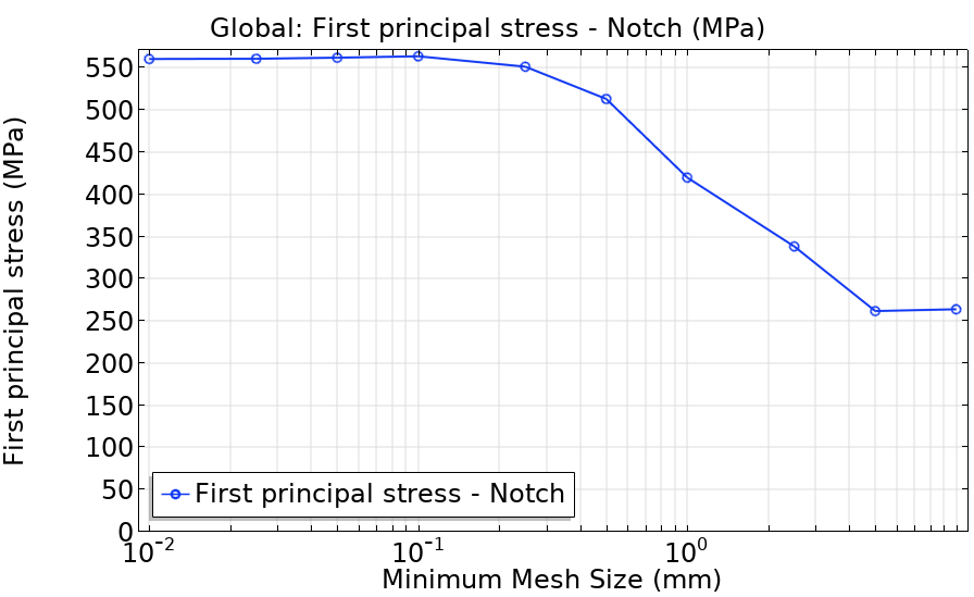
Max principal stress at the notch computed for different mesh sizes.
As shown above, correctly capturing the peak stress requires a mesh finer than 0.25 mm for this example, joining a 20-mm-thick plate and a 10-mm-thick plate. The notch stress method requires a very detailed mesh and that could limit its application to practical problems. Submodeling then provides an efficient way of determining local stress concentrations in large geometries.
Hot Spot Method
Another alternative to calculate the fatigue life of welded joints is the hot spot method. This method is based on a representative stress that is derived from an idealized stress distribution around the weld. This representative stress is sometimes called structural stress, geometric stress, or hot spot stress, which is the denomination that is used below. Generally, the stress perpendicular to the weld in the proximity of the toe has a nonlinear distribution along the thickness:
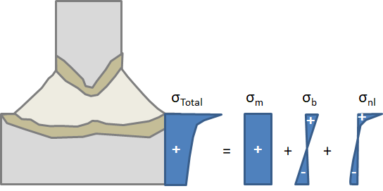
Total stress through the thickness and its decomposition to membrane, bending, and nonlinear stress.
The stress distribution through the thickness can be divided into three parts:
- Membrane stress, which is constant along the thickness
- Bending stress, which is distributed linearly through the thickness and is self-compensated
- Nonlinear stress, which is also self-compensated
The hot spot method is the surface stress obtained when the membrane and bending stress are combined. Using the previous model and the Stress Linearization feature available in COMSOL Multiphysics, we can plot the stress distribution through the thickness.


Path used to evaluate the stress distribution in the thickness direction (left). Stress distribution through the thickness and how this distribution varies with the mesh size (right).
As can be seen in the previous figures, the stress distribution in the thickness direction varies greatly with the mesh size, but the combination of membrane and bending stress remains more or less constant — even for coarse meshes. This approach still requires modeling the structure as a solid in order to obtain the through-thickness stress distribution.
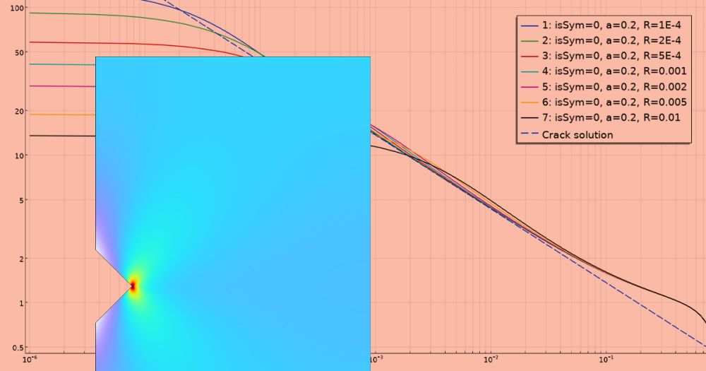
Another method to compute the same hot spot stress is from the extrapolation of surface stress from adjacent areas:


Path used to evaluate the stress distribution at the surface (green). Surface stress and how this distribution varies with the mesh size (right). The linearized stress is based on the stress at 10 mm and 20 mm away from the weld toe in this example.
We can see again that the notch stress depends strongly on the mesh size, but the stress distribution at a certain distance from the weld is identical for all mesh sizes. That means that coarse mesh sizes or even shell modeling could be used with this approach, and the obtained hot spot stress will be as precise as the one obtained with a solid modeling of the weld and a very fine mesh. This method requires a regular mesh with nodes and elements located at specific distances from the weld, which may require some time to set up in the model. The distances at which the stress should be obtained to extrapolate the hot spot stress are usually defined in the standards and depend on the dimensions of the welded components and the mesh size.
Final Remarks on the Fatigue Life of Welds
As we have discussed above, there are several methods available for the fatigue evaluation of welded joints. In this blog post, we have analyzed how COMSOL Multiphysics can be used with any of these methods, as well as the advantages and disadvantages of each of them.
| Method | Advantages | Disadvantages |
|---|---|---|
| Nominal stress |
|
|
| Notch stress |
|
|
| Hot spot stress |
|
|
Next Step
Learn more about how COMSOL Multiphysics can fit your welding and fatigue analysis needs. Contact us to evaluate the software.


Comments (4)
Van-The Than
April 13, 2020Dear Andres Garcia,
I am very interesting in model of the welding using Nominal Stress Method. Could you please share me how to model this? Thank you very much for your help.
Andres Garcia
April 20, 2020 COMSOL EmployeeDear Van-The Than,
The Nominal Stress Methods are specific to the design standard. In each of these standards you can find different descriptions of the loads, assumptions and combinations that contribute to the stress at the weld. It is important to note that the standard itself usually has some guidelines on the requisites of the finite element model.
The main comment here is that some of these standards require the use of nodal forces to reconstruct the nominal stress at the weld. As mentioned in the entry, an assembly in COMSOL allows you to obtain the nodal forces. Please send to support your specific question indicating the requirements of the standard and we can give you some feedback on how to implement it.
Van-The Than
May 4, 2020Dear Andres Garcia,
I am trying to model deformation and stress of butt welding joint. Could you please give me some suggestion for situation.
Thank you very much.
Andres Garcia
May 13, 2020 COMSOL EmployeeDear Van-The Than,
Modelling of butt welding is usually less challenging, as the butt welds tend to be full penetration welds and there is no need to explicitly capture the throat thickness. The nominal stress method could be obtained directly from the shell or solid elements representing the plate or could be derived from the nodal forces. Please contact support with the specific standard or method you would like to implement.
If you are interested in capturing the deformation and stress generated during the welding process, please take a look at the links in the “Introduction to the Welding Process” section.
Thank you for your comments.