

Not too long ago, my colleague Jennifer wrote a blog post about the Cross Cancer Institute, and the research being conducted there into the design of a new device for treating cancerous tumors. The device, known as the Linac-MR, is revolutionary due to its ability to both image and treat cancer cells simultaneously — a capability that had previously been regarded as near impossible due to the conflicting physics interactions involved. Such a device would allow for extremely precise radiation treatment because it could both detect and compensate for body movement during treatment, therefore allowing for accurate targeting even in moving tumors, such as those in the lungs, liver, stomach, etc. Some aspects of the device’s design were outlined in the COMSOL News story “MRI Tumor-Tracked Cancer Treatment”, however, in addition to the simulation work described in the article, I want to share a bit more about the research here, and point you to a few more resources that discuss this innovative design.
Mitigating Electromagnetic Interactions
Before delving into some of the additional simulations and experiments conducted by the group, I first want touch on what it is that makes this device so revolutionary. There are many different factors that make designing a device that can both image and treat a cancerous tumor complex. One of the main reasons for this is the electromagnetic interactions that occur between different components of the device. Many current cancer treatments use a linear particle accelerator (linac) to generate and direct radiation beams toward a target. The target, i.e. the cancerous tumor, is first located by imaging the tumor using a magnetic resonance (MR) scanner, which, in current practices, can be done days or even weeks prior to radiation. This is because, when used simultaneously, these two systems adversely affect the performance of the other. The electromagnetic waves generated by the linac impede the MR scanner’s ability to interpret RF signals needed to create images, while the MR scanner can deflect the linac’s electron beam, potentially causing it to irradiate healthy tissue.

Configuration of the Linac-MR, where the MR scanner moves in
the longitudinal direction around the treatment table.
As was explained in a previous blog post, researchers from the Cross Cancer Institute tested a few different orientations of the linac and MR scanner. Additionally, the team used simulation to explore different designs for a shielding plate to prevent unwanted electromagnetic interactions.
Considerations for the Linac-MR
There were quite a few other things the team considered when creating the final design. I explained a few of these in an article titled “Hybrid Linac-MR: Image-Guided Radiation Therapy Delivered in Real-Time“, which appeared in this month’s issue of Microwave Journal.
One of the main constraints that drove the team to further optimize and refine the design of the Linac-MR was the size of the device. Not only does the success of the Linac-MR depend on preventing electromagnetic interactions as described above, but the device also needs to be able to function within the space allotted for such devices in hospitals and treatment centers. In order to keep harmful radiation as far away from both people and equipment, many radiation therapy rooms are located in the basement. This means that the Linac-MR needed to be below a certain size, since expanding such a basement room would require too many resources to be a feasible option. Designing a “small” Linac-MR required further optimization and experimentation to be conducted on the linac used in the device.
In order to treat the full range of cancer types, a 1.5 meter 10 MeV waveguide is required for the linac. Additionally, in order to prevent interactions that are difficult to shield from MRI, the waveguide would need to be positioned vertically above the device. This means that, in order to fit inside a standard treatment room, the length of the waveguide needed to be reduced while still maintaining the strength of the electron beam. The team of researchers first estimated that 70 cm was the shortest 10 MeV waveguide that could be designed, however, by performing additional simulations, they were able to reduce the length of the waveguide down to 30 cm, as shown below.
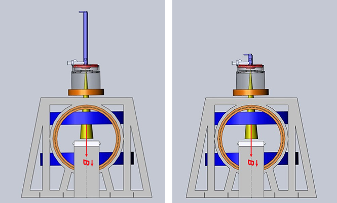
Left: 1.5 meter 10 MeV waveguide positioned vertically above the treatment table. Right: Shortened, 30 cm waveguide.
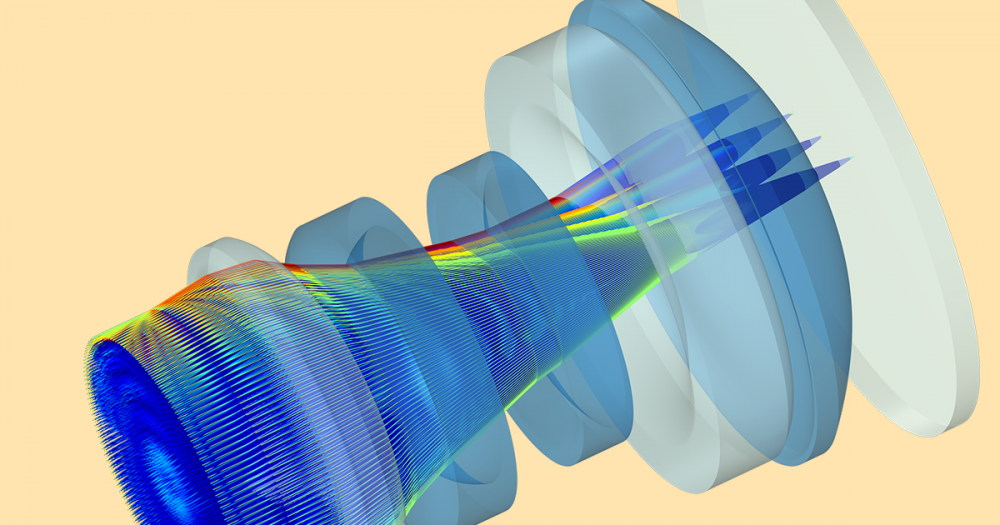
When designing the 30 cm waveguide, the team began with a 6 MeV waveguide previously designed by a member of the group. Using simulation to explore different shapes of the RF cavities within the waveguide, the team was able to find a geometry that allowed for a 10 MeV energy source to be used on the shorter waveguide.

Simulation of the short, 10 MeV waveguide showing the electromagnetic field
distribution within the device.
Additional Resources
- Read the full article from Microwave Journal, “Hybrid Linac-MR: Image-Guided Radiation Therapy Delivered in Real-Time“
- Explore technical papers and more on the Linac-MR Project website


Comments (0)