

COMSOL Multiphysics version 5.1 introduces a new tutorial model of a UHF RFID tag. RFID tags allow you to identify and monitor both inanimate objects and living creatures through the use of electromagnetic fields. The UHF RFID tag has a wider range than other types of RFID tags and is often used to identify animals. We can evaluate the performance of the tag through an analysis of the electric field and far-field radiation pattern.
Using RFID Tags on Animals
Radio-frequency identification (RFID) tags allow objects to be identified without the use of a wired connection. They can be used in applications ranging from ID badges to animal maintenance (or a more creative and fictional use: as part of a robotic butterfly). Scientists also use RFID tags to track whale sharks, the largest fish in the sea. Through this process, they hope to learn more about these gentle creatures. A more common use of RFID tags is on farm animals. Farmers will tag their animals (such as cows) in order to verify that they own them, protect against theft, and identify animals in the case of a disease outbreak.

A cow with an RFID tag in her ear. (By Man vyi. Licensed under public domain, via Wikimedia Commons).
The UHF RFID Tag
There are three kinds of RFID tags:
- Low-frequency (LF) range
- High-frequency (HF) range
- Ultra-high-frequency (UHF) range
A UHF RFID tag has many advantages over other RFIDs, making it suitable for monitoring animals. Unlike the HF alternative, the UHF RFID tag can be read at near and far distances and can thus work for a wider range of uses. These tags can generally also transfer data faster than their LF and HF counterparts and offer competitive prices.
Modeling the UHF RFID Tag Design (Animal Not Included)
With COMSOL Multiphysics version 5.1, we are offering a new tutorial model to help you get started with the simulation of passive UHF RFID tags. Let’s have a look at what is included in the tutorial.
As is a common practice in RFID tag design, the antenna in our model is folded in a meandered path in order to make the overall tag smaller. The antenna is made up of copper traces patterned on an FR4 board. A lumped port represents the microchip that will be used to excite the tag and analyze the input impedance of the tag’s antenna. Our lumped port has a reference impedance of 50 Ω. Next to the meander line is another copper strip, which we use to control the impedance.
All of these components are covered by a yellow low-dielectric PTFE casing to look similar to the tag we saw in the cow’s ear, above.
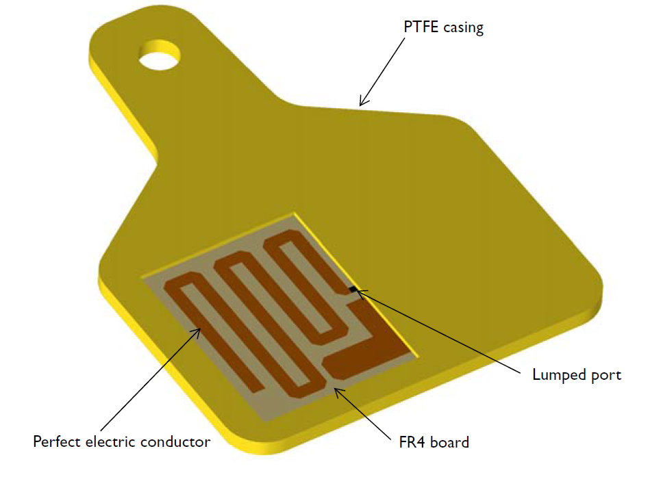
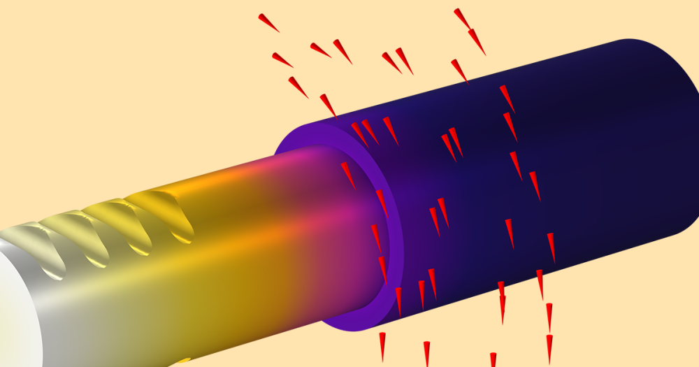
The geometry of a UHF RFID tag with one half of the circuit board exposed. The lumped port represents the chip.
Since we set our RFID tag’s operating frequency to 915 MHz and the copper traces are thicker than the skin depth, the metallic aspects of our design can be modeled as a perfect electrical conductor (PEC). You cannot see this in the figure above, but surrounding our whole model is a spherical air domain, which is itself encompassed within perfectly matched layers (PMLs). All outgoing radiation is absorbed by the PMLs.
We approach this simulation in a non-conventional way, by choosing a power wave reflection coefficient term to deal with the complex impedance. This allows us to evaluate the matching properties in our RFID tag.
Note that we will skip ahead to the results in the next section. To learn how to build this tutorial model step-by-step, please visit the Application Gallery.
Evaluating the Tag Performance
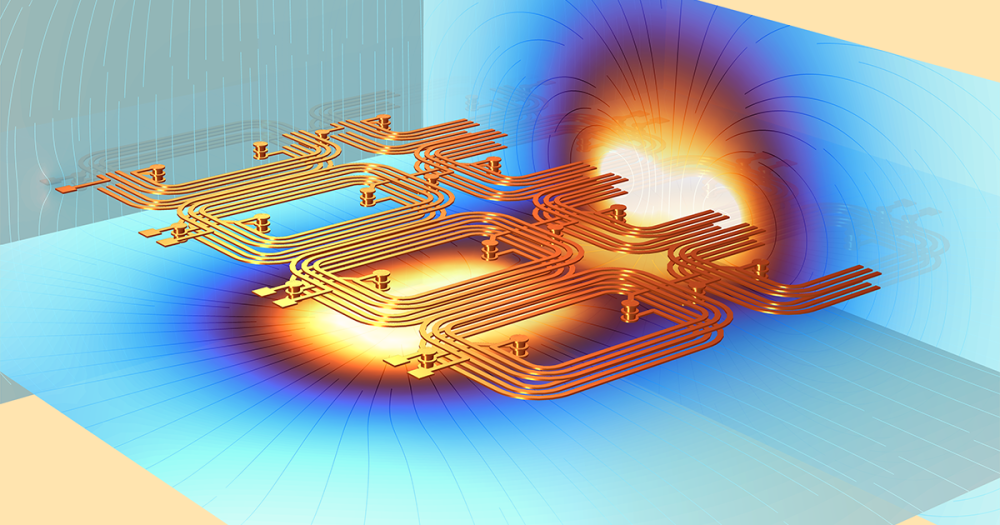
After setting up and solving our model, we can analyze the results to evaluate how well the tag design performs. To understand how the electric field is distributed throughout the antenna, we can study the electric field norm plot. When the antenna is resonant, strong fields will be observed at each end and some of the outer edges of the meander line. The tag’s range is determined by the impedance match between the antenna and the chip.
First, we analyze the default electric field (E-field) norm on an xy-plane to determine where in the tag the field is confined. As we can see in the plot below, the electric field is symmetrical along the meander line and in the space between the meander line and the impedance matching strip. This is ideal because a symmetric field may generate a symmetric radiation pattern.
With a symmetric radiation pattern (in this model, it’s omni-directional on one plane), we can easily expect what the ideal angular configuration of the tag is. To put it in terms of our example use case, this information will guide us on where to attach the tag on the cow and where to locate the RFID reader in order to ensure that we monitor all of the cows.
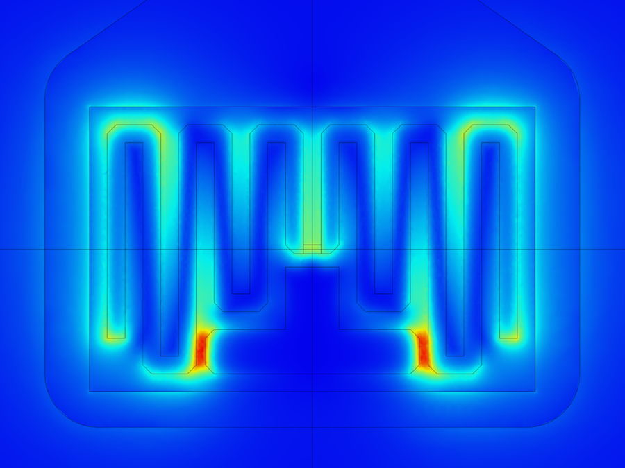
The E-field norm plot of our UHF RFID model for the full-sized circuit board.
Next, we can take a look at the far-field radiation pattern. The pattern will be familiar to simulation engineers who work on other antenna designs too; the radiation pattern looks a lot like that of a half-wave dipole antenna.
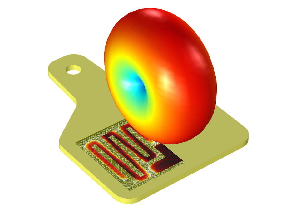
The far-field radiation pattern of our UHF RFID tag model.
Through our simulation, we discover that the power wave reflection coefficient of the tag is below -15 dB with respect to the chip impedance 18+j124 Ω. This means that when the delivered power to the RFID chip re-radiates through the tag, less than -15 dB of power will be reflected back to the chip. Compare this with a commercial off-the-shelf antenna of mediocre performance, which would provide -10 dB. Given that, our design is not excellent, but it is acceptable. Since the radiation pattern is omni-directional around the meander line, its response is almost the same at any direction on one plane. This suggests that our tag is robust and reliable.
If you are a design engineer at an RFID tag company, you can turn to COMSOL Multiphysics simulation software to evaluate how your UHF RFID tag will perform. Get started by downloading the tutorial model below.
Tutorial Downloads and Further Reading
- Tutorial model: Numerical Modeling of a UHF RFID Tag
- Tutorial model: An RFID System
- Blog post: RFID Tag Read Range and Antenna Optimization
- Blog post: A Creative Take on RFID Tags

Comments (0)