
Steel, an iron-based alloy, is a widely used material because of its high strength and low cost. It is used in various applications, ranging from automobiles, buildings, wind turbines, and infrastructure to mechanical equipment, appliances, and knives. Most steel products undergo some heat treatment during their manufacture. One such treatment is quenching. Using the COMSOL Multiphysics® software, you can simulate the quenching process used in your manufacturing process. Let’s take a look at one example…
Carburization and Quenching
Gears are a fundamental engineering component and are vital to many everyday objects, like car transmissions and washing machines, because they can exchange speed for torque (or vice versa). If it’s a mechanical device and it moves, chances are that gears are involved.
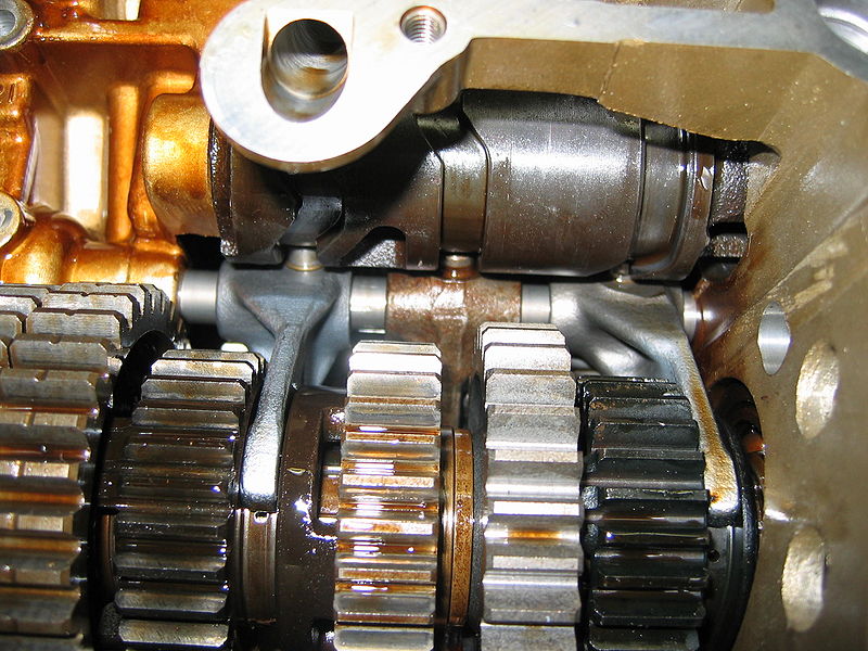
Spur gears in a power transmission system. Image by Gérard Delafond. Licensed under CC BY-SA 3.0, via Wikimedia Commons.
Power-transmitting gears are typically hardened to improve their fatigue durability and wear resistance. Different hardening processes can be used, including carburization, nitriding, and induction hardening, followed by quenching. In the tutorial model discussed here, you can use simulation to examine how carburization followed by oil quenching affects the residual stress state in a steel gear.
Modeling the Carburization and Quenching of a Spur Gear
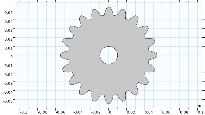
The tutorial uses the geometry of a classic spur gear. The 2D steel spur gear has 20 teeth and a diameter of 200 mm.
The material is modeled as a generic steel, where the temperature-dependent thermal and mechanical material properties of the individual metallurgical phases are averaged into effective material properties by the Austenite Decomposition interface, available in the Metal Processing Module.
The process of carburization entails subjecting a heated component to a carbon-rich environment. Carbon diffuses into the component’s surfaces, which leads to increased hardness and wear resistance. Here, the transient Fick’s law (diffusion) is used to simulate a simple carburization process. The image below shows the carbon concentration after carburization. Near the surfaces, the carbon concentration is higher compared to the interior.
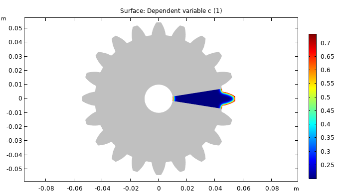
Carbon concentration in the gear after carburization.
A change in carbon concentration alters the phase transformation characteristics during quenching. In this model, only the martensitic transformation is considered. With an increased carbon concentration, the onset of martensitic transformation occurs at a lower temperature. This is modeled using a carbon-concentration-dependent martensite start temperature, M_\mathrm{s}.
Once the gear has been carburized, it is oil quenched.
In this model, we simulate that the gear is rapidly immersed into the quenching oil, and held there. During the transient process of cooling, distortions and stresses develop in the gear.
Note that the quenching oil isn’t explicitly modeled in this tutorial; instead, heat exchange is modeled using a convection boundary condition with a temperature-dependent heat transfer coefficient. The temperature of the quenching oil in this example is 80°C. Even though the quenching process is time dependent, it’s quasistatic as far as structural mechanics is concerned, and so it is modeled as such.
Examining the Results
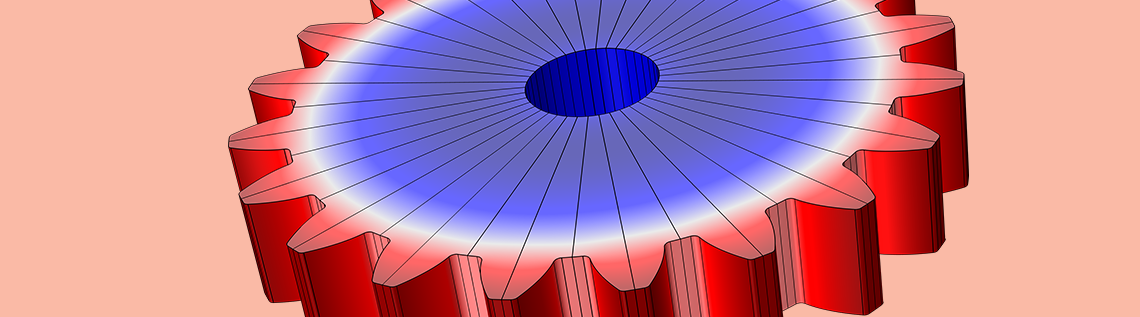
After simulating the quenching of a steel gear, distortions and residual stresses can be visualized. During service, gear bending fatigue can initiate at the roots of the gear teeth. Residual compressive stresses in these regions can reduce the risk of mechanical fatigue. The image below shows that stresses are compressive (blue) near the roots.
While these are the results for this specific tutorial, the residual stress depends on the cooling process: Different cooling scenarios can lead to drastically different results.
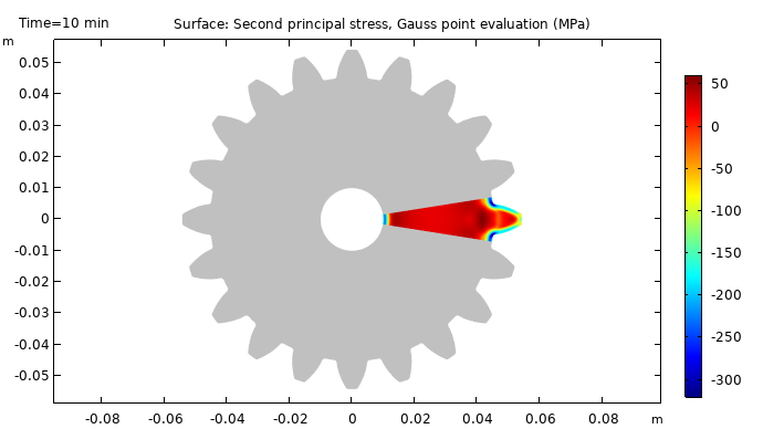
Residual stress state in the gear after quenching.
Being able to model and simulate carburization and quenching can help manufacturers reduce the number of trials. Simulation also makes it easier to try out different quenching methods on modeled gears made from different alloys. Visualizing the residual stresses allows for a deeper understanding of the effects that different processes have on the final result.
Next Steps
Try modeling the carburization and quenching processes yourself. Click on the button below to go to the Application Gallery, where you can download the documentation and the MPH-file.
Learn more about the Metal Processing Module in this blog post: Introducing the Metal Processing Module.

Comments (0)