

In certain cases, traditional modeling approaches and simplifications lead to models that do not represent a structure accurately. One example is structures in contact with fluids where the dynamic response of the structure is substantially altered by the presence of the fluid, such as a fuel tank. Here, we will compare a traditional modeling approach and a multiphysics modeling approach for analyzing a fuel tank. Keep reading to find out which modeling option provides more accurate results…
The Optimal Way to Model Fuel Tank Vibration
When a vehicle is turned on, different components, like the engine, suspension, and transmission, generate vibrations that propagate through the structure of the vehicle. These vibrations can produce significant stress in the structural components and lead to fatigue failure after a large number of cycles. To accurately predict the dynamic behavior of a fuel tank, it is critical to consider the influence of the fluid on the structure.
The Fuel Tank Vibration tutorial model demonstrates the modeling and analysis of a fuel tank that is partially filled with fluid. In this example, two different modeling approaches are used to represent and analyze the fluid in the tank:
- A traditional approach in which the fluid mass is dispersed through the tank’s wetted surface
- A multiphysics method that specifically models the acoustic pressure in the fluid
The traditional method uses the Structural Mechanics Module, while the multiphysics approach uses both the Structural Mechanics Module and the Acoustics Module; both are add-on products to the COMSOL Multiphysics® software.
The traditional method is a simplified approach that disregards the dynamic characteristics of the fluid and only considers its mass. The multiphysics approach, on the other hand, accounts for the entire mass of the fluid in the tank and the pressure waves in the fluid mass. This analysis focuses on small amplitude vibrations transmitted through the vehicle structure and transformed into small perturbations of pressure in the fluid. The large amplitude and low-frequency movement of the fluid in the tank caused by the vehicle acceleration, also known as sloshing, is discussed in the Two Phase Flow with Structure Interaction model. Multiphysics simulation enables you to visualize and determine the dynamic characteristics of a partially filled fuel tank, such as discrepancies in the stress, frequencies, damping factors, and mode shapes.


Added mass representing the fluid used in the traditional modeling approach (left) and the acoustic domain mesh used in the multiphysics approach (right).
The modeled fuel tank is made of 1.6 mm aluminum walls, and has an approximate volume of 32.6 l — of which 19.6 l are filled with fluid. It is secured to the surrounding structure with a foam block and 3 straps made of 2 mm steel plates. The foam block helps minimize the movement of the fuel tank in the vehicle, which prevents squeak and rattle noises, as well as surface wear effects.
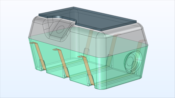
Geometry of a fuel tank partially filled with fluid.
The model assumes the fluid in the tank is diesel fuel, and the tank is submitted to a vertical acceleration in the areas connected to the surrounding structure.


Highlighted in blue are the 3 steel straps (left) and the parts where foam is used (right).
How do the results of the two modeling approaches compare?
Simulation Results
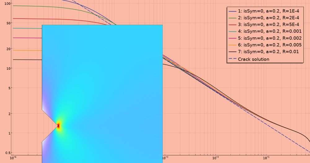
The frequency response function, or FRF, is analyzed on one point of a fuel tank strap in both the traditional model and the multiphysics model (shown below). The FRF can be used to obtain the stress response of the fuel tank against a frequency-dependent load or other loads, like one specified through a power spectral density (PSD) function. The frequency response of mechanical systems is discussed in-depth in a previous blog post.


The measuring point on the fuel tank straps is shown in blue.
By analyzing the FRF in both models, it can be seen that the two approaches have significantly different modal content. This is further confirmed with a modal analysis, which shows discrepancies in the frequencies, shapes, and damping of the first ten modes.


Measuring point location on the strap (left) and stress FRF with the 2 different modeling approaches (right).
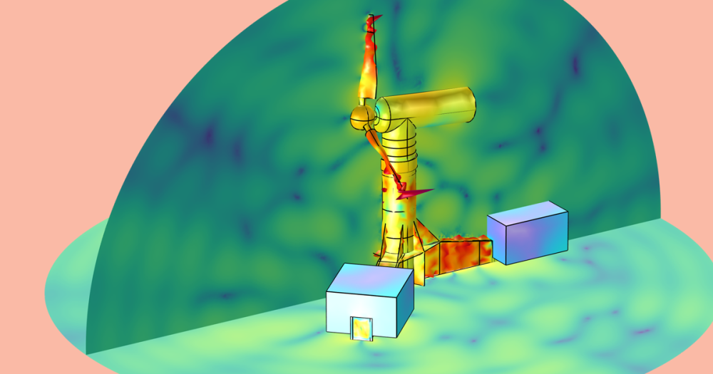
In the results below, you can see a stress comparison at two different frequencies for both modeling methods. The structure with the added mass stands for the traditional approach and the structure with acoustics represents the multiphysics approach.
At a frequency of 88.9 Hz, there is no stress in the fuel tank modeled with the traditional method, but in the fuel tank modeled with the multiphysics approach, there is a significant amount of stress. However, at a frequency of 128.5 Hz, there is stress present in the traditional model, but no stress in the multiphysics model.


Stress comparison at 88.9 Hz (left) and 128.5 Hz (right) of both modeling approaches.
The two methods show substantial differences when simulated and analyzed, demonstrating how important it is to accurately capture the vibroacoustics behavior when predicting stress or fatigue life on fluid-filled cavities such as fuel tanks.
Try It Yourself
Check out the Fuel Tank Vibration tutorial model by clicking the button below.

Comments (0)