support@comsol.com
Fuel Cell & Electrolyzer Module Updates
For users of the Fuel Cell & Electrolyzer Module, COMSOL Multiphysics® version 6.2 introduces a new pore-wall interaction model for gas diffusion in porous media (Knudsen diffusion), as well as functionality to define anisotropic tortuosities and the ability to define contact resistances. Read about these updates and more below.
Pore-Wall Interaction and Knudsen Diffusivities for Gas Phase Mass Transport
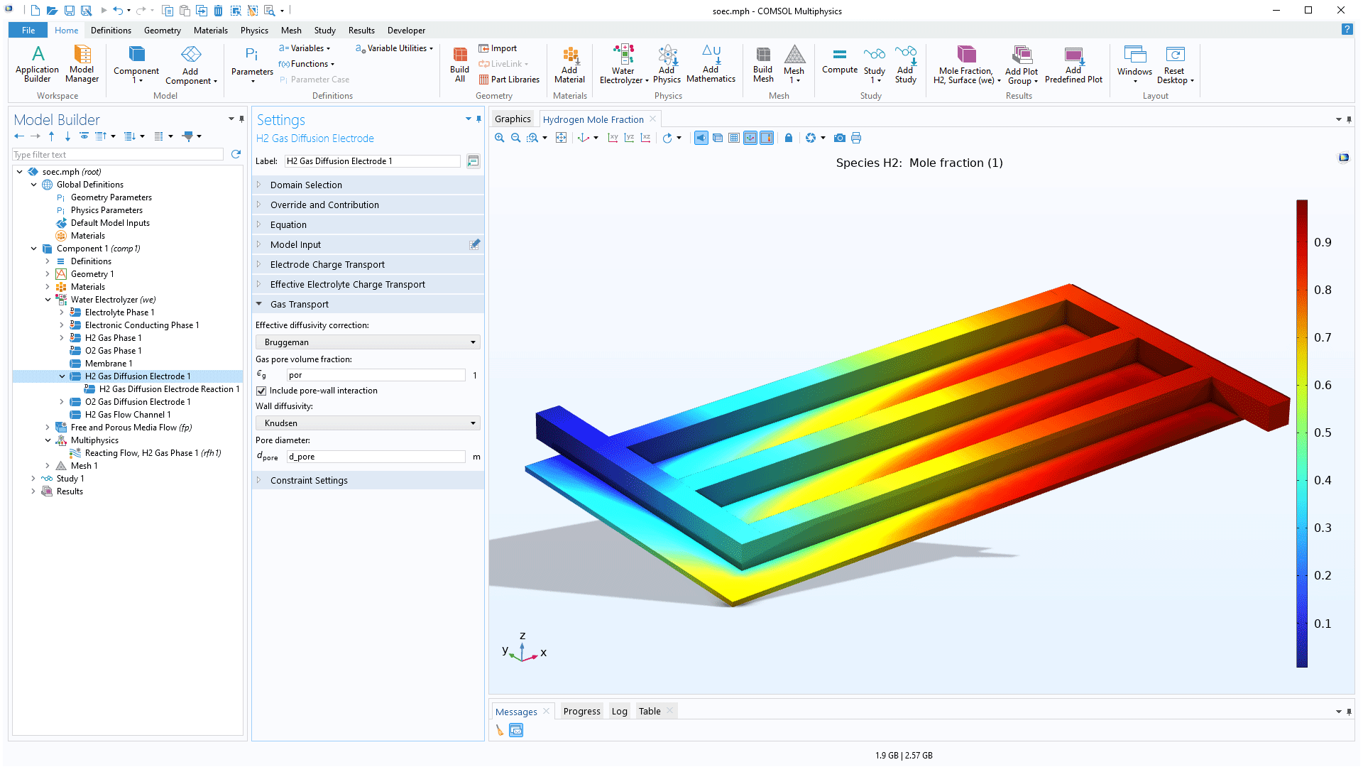
For the Hydrogen Fuel Cell and Water Electrolyzer interfaces, the H2 Gas Diffusion Layer, O2 Gas Diffusion Layer, H2 Gas Diffusion Electrode, and O2 Gas Diffusion Electrode features include a new Include pore-wall interaction check box in the Settings window. This feature can be used to define the wall diffusivity using either Knudsen diffusivity or user-defined values. Pore-wall interactions typically become more important at high temperatures in combination with small pore sizes, for example, in solid-oxide-electrolyte-based gas diffusion electrodes. The Current Density Distribution in a Solid Oxide Fuel Cell tutorial model and both versions of the Solid Oxide Electrolyzer Using Thermodynamics tutorial model have been updated to showcase this new feature.
Anisotropic Tortuosities
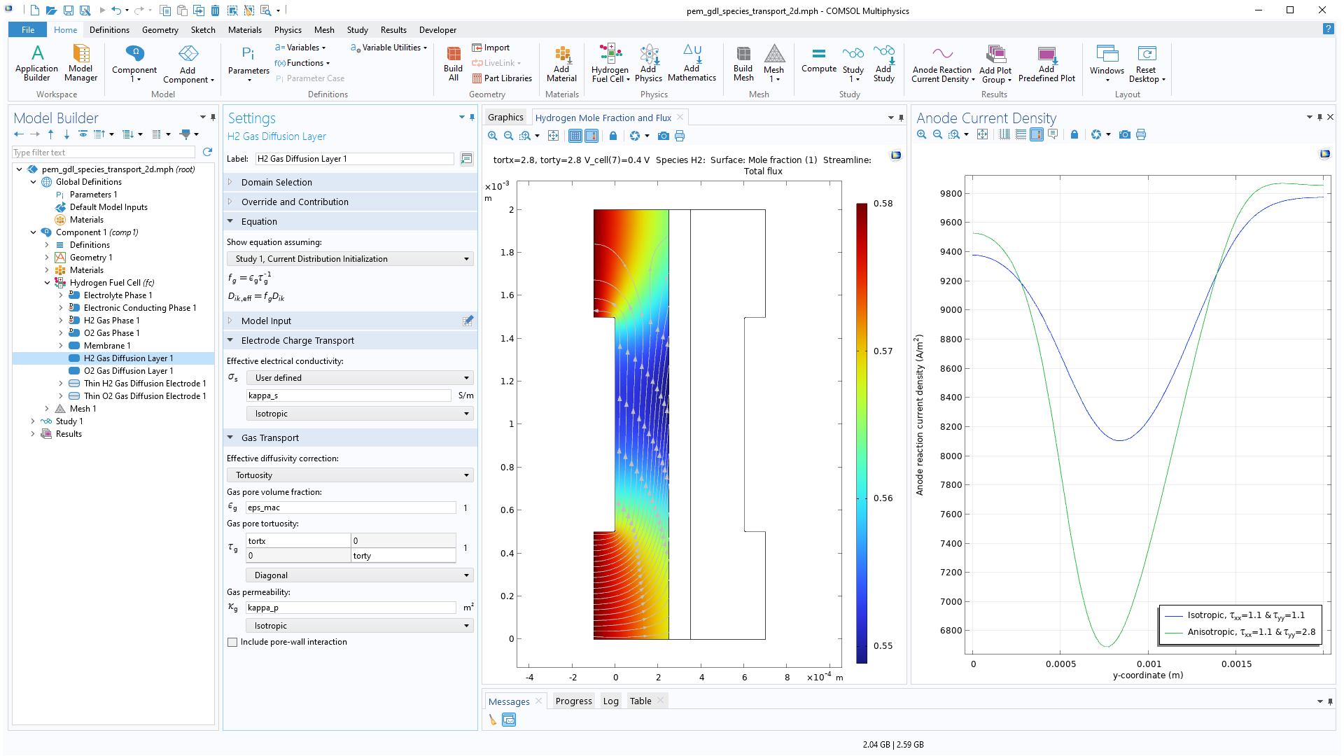
For the Hydrogen Fuel Cell and Water Electrolyzer interfaces, anisotropic tortuosities can now be used in the H2 Gas Diffusion Layer, O2 Gas Diffusion Layer, H2 Gas Diffusion Electrode, and O2 Gas Diffusion Electrode nodes to compute effective diffusion coefficients. Additionally, the Transport of Concentrated Species interface now supports anisotropic tortuosity in porous media. This new functionality provides the ability to specify different in-plane and through-plane effective gas diffusivities. You can view this functionality in the updated Species Transport in the Gas Diffusion Layers of a PEM tutorial model.
Contact Resistance
For the electrochemistry interfaces, it is now possible to include contact resistance in the Electric Ground, Electric Potential, Electrode Current, and Electrode Power external boundary conditions. This functionality circumvents the need to add a thin domain to describe a poorly conducting layer, which would otherwise result in very dense mesh, with many additional degrees of freedoms. The ability to add contact generates a low computational load while retaining accuracy.
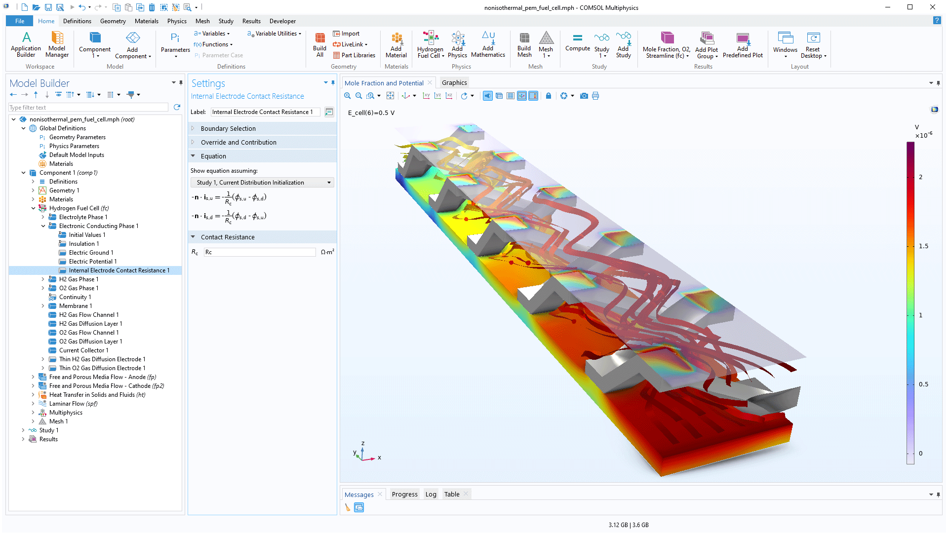
This functionality has also been added to the Hydrogen Fuel Cell and Water Electrolyzer interfaces. In addition, the new Internal Electrode Contact Resistance subnode can be added to internal Electrode Conducting Phase boundaries, for instance, between a Gas Diffusion Layer and a Gas Diffusion Electrode. Contact resistances on electrode–electrolyte interfaces may now also be defined using the Film resistance section in the settings of the following features:
- H2 Electrode Surface
- O2 Electrode Surface
- Internal H2 Electrode Surface
- Internal O2 Electrode Surface
- Thin H2 Gas Diffusion Electrode
- Thin O2 Gas Diffusion Electrode
You can see these updates in the Nonisothermal PEM Fuel Cell and Low-Temperature PEM Fuel Cell with Serpentine Flow Field tutorial models.
New Interfaces for Coupled Free and Porous Media Flow
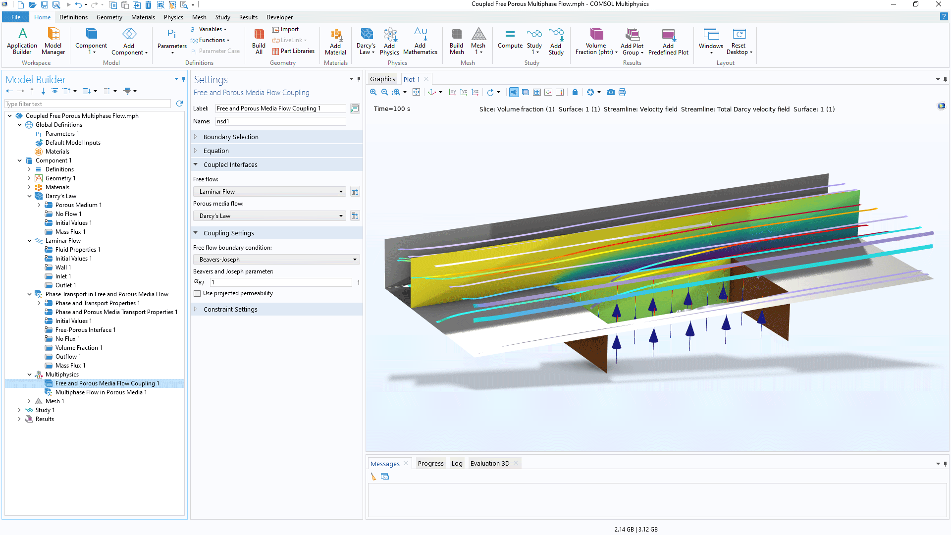
There is a new Free and Porous Media Flow, Darcy multiphysics interface that, once selected, adds a Darcy's Law interface, a Laminar Flow interface, and a new Free and Porous Media Flow Coupling multiphysics coupling to the model tree. This multiphysics interface can be used with the new Phase Transport in Free and Porous Media Flow interface to seamlessly model multiphase transport in free and porous media flow.
Updated Tutorial Model
COMSOL Multiphysics® version 6.2 brings an updated tutorial model to the Fuel Cell & Electrolyzer Module.
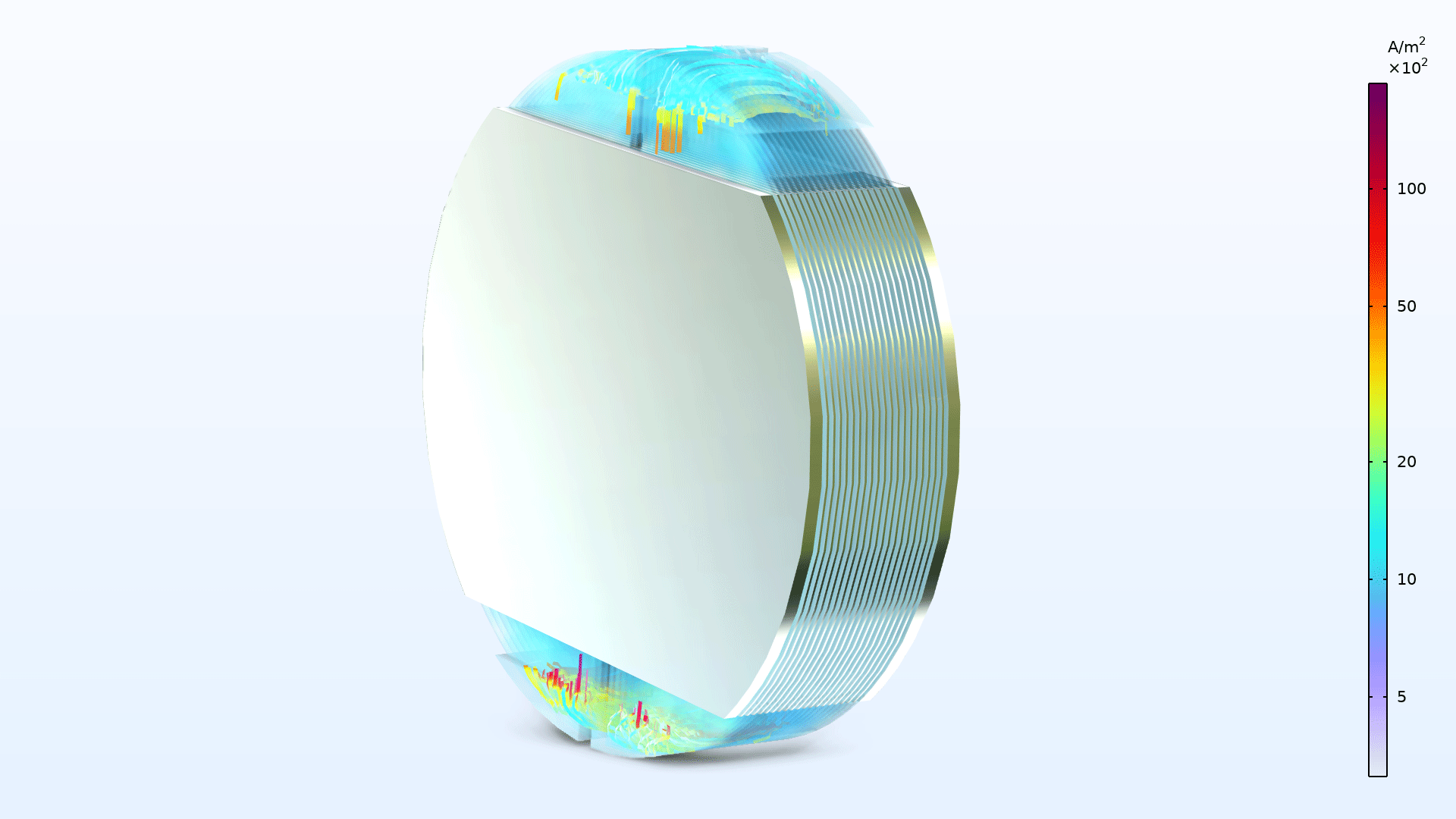
Shunt Currents in an Alkaline Electrolyzer Stack
Application Library Title:
aec_shunt_currents
Download from the Application Gallery