
You’re standing in a lab full of beakers containing different colored liquids. While it may look like something out of a cartoon, this is a lab for researching vanadium redox flow batteries (VRFBs). Unlike conventional batteries, the chemical energy in VRFBs is contained in liquid electrolytes that are stored in external tanks and pumped through the cell to convert to or from electrical energy. By advancing VRFB designs, engineers can improve grid energy storage and the reliability of renewable energy.
What Are Vanadium Redox Flow Batteries?
A VRFB is a rechargeable flow battery consisting of an ion exchange membrane that separates positive and negative electrolyte solutions. Typically, the membrane only allows for protons to travel between the two cell compartments.
In the battery’s charging period, vanadium ions in the positive electrolyte are oxidized and lose electrons. Meanwhile, vanadium ions in the negative electrolyte are reduced and gain electrons. The electrons move from the positive to negative side of the cell via the external electrical circuit. When charging, a voltage must be applied to drive the electrons through the circuit — the electrical energy put into the cell through this voltage is converted to chemical potential energy stored in the tanks by causing the oxidation and reduction reactions. Then, in the discharging period, the reactions proceed spontaneously in the opposite direction, and the corresponding flow of electrical current can be used to extract the stored energy.
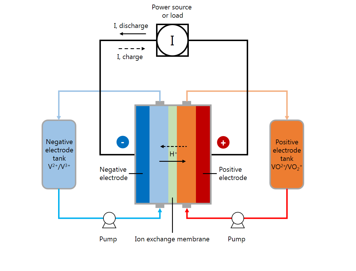
A schematic of a vanadium flow battery system.
Vanadium is a good choice of chemical element for use in these batteries due to its ability to exist in a wide range of different oxidation states in a solution. By using vanadium in both tanks, VRFBs also avoid the cross-contamination issues that affect other redox flow batteries (RFBs).
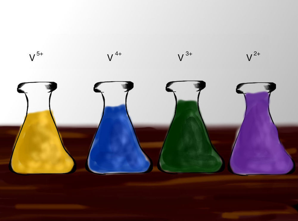
Labs studying VRFBs may include colorful beakers full of vanadium in different oxidation states.
Lithium-ion batteries are the common rechargeable battery choice for consumer and other small-scale applications. But for large-scale applications, VRFBs have a few advantages compared to lithium-ion batteries:
- The ability to be scaled up more easily
- Longer lifetimes
- The ability to operate constantly for 20 years or more
- Increased safety, as VRFBs don’t pose a fire hazard
By using larger electrolyte storage tanks, VRFBs can also offer a seemingly limitless energy capacity and have the potential to store hundreds of megawatt-hours of energy.
These benefits mean that engineers can use VRFBs for large-scale energy storage, helping to increase the stability of power grids. The improved stability is because the batteries can handle large increases in demand during peak periods by quickly accessing stored electrical power.
VRFBs are especially useful in conjunction with renewable energy sources — such as wind and solar — that suffer from intermittency issues. For example, wind power is only generated when the wind is blowing, but we still need energy when there is no wind. VRFBs could help to level out this variable production by cheaply storing excess energy for later use when the renewable source cannot provide power. Combined with flow batteries, renewable energy sources could provide an uninterrupted supply of energy, making them more reliable.
Studying and Optimizing VRFBs with Simulation
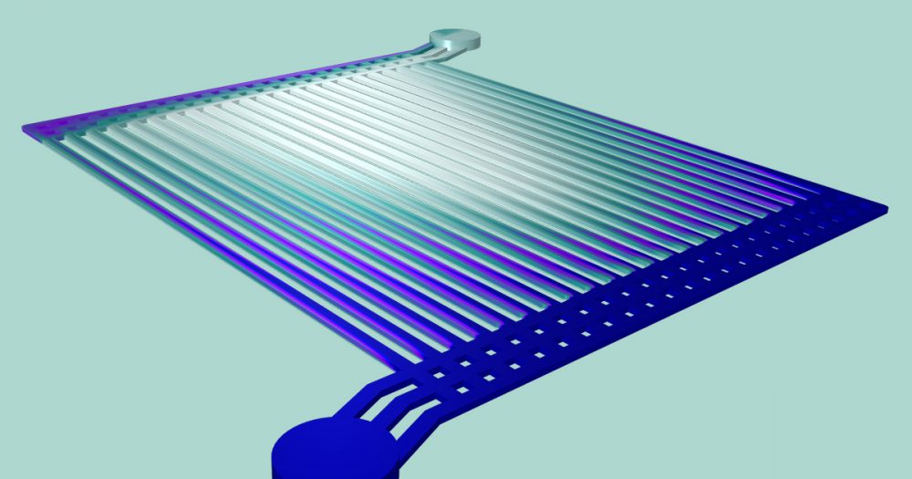
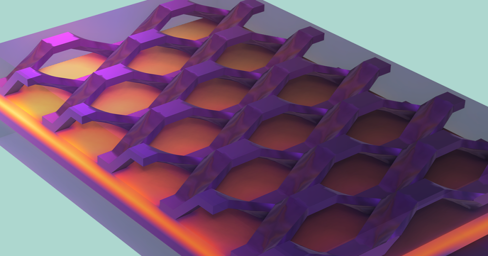
To improve VRFBs and address some of their existing shortcomings, such as their low energy density and functional temperature range, engineers can use the COMSOL Multiphysics® software. For instance, researchers from Xi’an Jiaotong University built a 3D VRFB model to analyze the fluid pressure, electric potential, current density, and overpotential during the operation of a VRFB. Their goal was to analyze the transport problem and reaction kinetics along with the initial boundary conditions and underlying assumptions. They hope that their model can be used to improve VRFB stack designs and so widen system operating conditions.
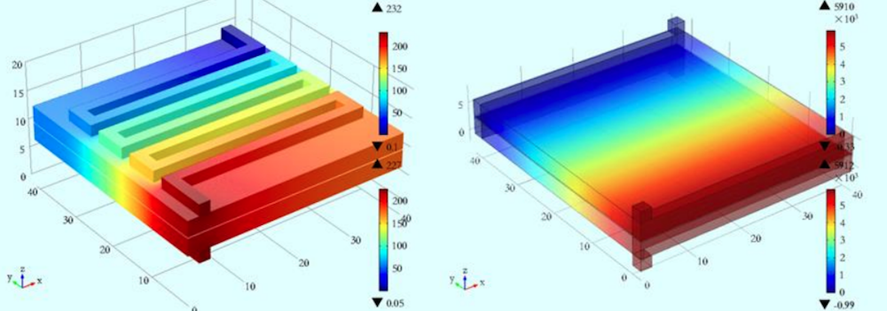
Studying the pressure distribution with a serpentine flow field (left) and no flow field (right). Image by Q. Wang, Z. Jiang, D. Lu, and Z. Qu and taken from their COMSOL Conference 2015 Beijing poster.
At Drexel University, researchers used simulation to address crossover in VRFBs, which occurs when the vanadium ions themselves cross the ion exchange membrane during battery operation. This dissipates the stored chemical energy without yielding any corresponding power to the electrical circuit, and so poses a major limiting factor to the efficiency and long-term charge/discharge stability of the system.
To accurately evaluate how crossover affects VRFB performance, the team created an electrochemical model with COMSOL Multiphysics. Their simulation results agree well with experimental data, and this model can successfully analyze the transient performance as well as the spatial distributions of the species concentrations, potentials, and reactions in both the membrane and electrode.
Of course, these are only a few examples of modeling VRFBs. To further study this promising type of flow battery, we can use a simplified model based on published works.
Modeling a Vanadium Redox Flow Battery with COMSOL Multiphysics®
A simple 2D VRFB example can be composed of an ion exchange membrane that separates two cell compartments with different electrode reactions and ion compositions. As such, the model has three domains:
- Ion-exchange membrane
- Negative porous electrode, filled with a negative electrolyte that contains H+, HSO4–, SO42-, V3+, and V2+ ions
- Positive porous electrode, filled with a positive electrolyte that contains H+, HSO4–, SO42-, VO2+, and VO2+ ions
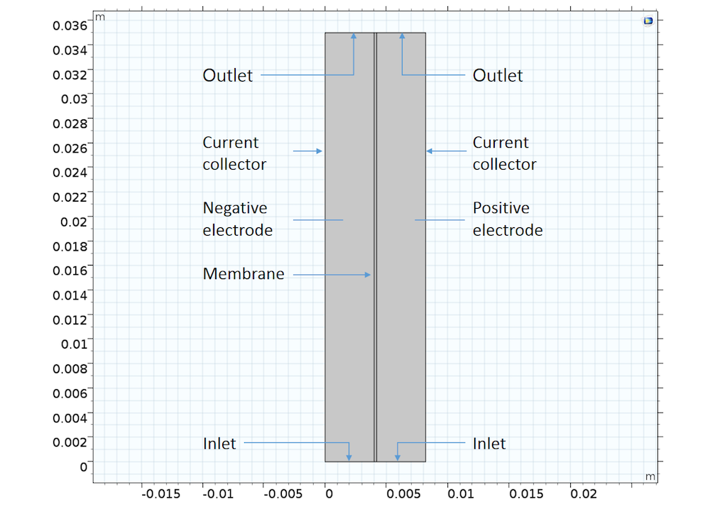
VRFB model geometry showing the three different domains.
When running this model, we feed a flow of electrolyte consisting of sulfuric acid and a vanadium redox couple to each side of the cell. The liquid enters the bottom of the cell at a constant velocity in the y direction and flows through the porous electrodes, flowing in parallel in both half-cells on either side of the membrane. The liquid then exits the cell at the top boundary.
We can use this model to solve for a stationary case when given a set of inlet concentrations and an electrical loading condition between the electrodes. In this example, the flow battery is operating in discharge mode with an average current density of 100 mA/cm2 at the current collectors.
For more detailed information about setting up and solving this example, check out the model documentation for the Vanadium Redox Flow Battery tutorial.
Examining the VRFB Simulation Results
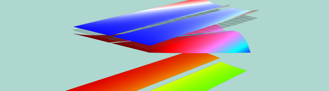
Let’s first look at the concentrations of the ions produced during the discharge step: these are V3+ in the negative electrolyte and VO2+ in the positive electrolyte. You can see that the concentration of both of these ions increases near the current collectors and towards the outlet. As for the V2+ in the negative electrolyte and VO2+ in the positive electrolyte, these ions deplete along the flow direction close to the current collectors.


The concentration of V3+ and VO2+ ions (left) as well as V2+ and VO2+ ions (right).
We can also study the electrode reaction rate, which depends on the combination of electrical resistance, electrode kinetics, and electrode thermodynamics in the cell, as well as mass transport of the vanadium ions due to diffusion and convection. In a cross section perpendicular to the flow, it is clear that the maximum electrode reaction source occurs at the current collectors and the minimum occurs in the middle of the electrodes.
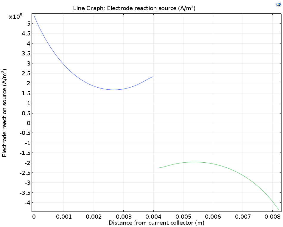
Plotting the porous electrode reaction source along a horizontal line at y = hcell/2.
Finally, let’s take a closer look at the sulfuric acid electrolyte. While sulfuric acid (H2SO4) loses one proton readily to form HSO4–, the loss of the second proton to form SO42- depends on an acid-base equilibrium whose position will be influenced by the local proton concentration (pH). By considering the transport of protons through the ion-exchange membrane as well as the mass transport and acid-base reactions of each of these species, the rate of acid-base dissociation as well as the overall concentration of the different species can be predicted, providing more detailed insight into the chemical conditions in the cell.
When examining the dissociation reaction rate of the sulfuric acid (left image below), we see that the rates are highest close to the boundaries; likewise, the local concentrations of the sulfuric acid (right image below) show that gradients are only found close to the membrane. This happens because the consumption or release of protons at the membrane boundaries to carry ionic current will perturb the acid-base equilibrium, and so also change the local ionic strength in the electrolyte.


The logarithm of the sulfuric acid dissociation rate (left) and the sulfuric acid species activity along a horizontal line placed at y = hcell/2 (right).
Next Steps and More VRFB Resources
To try this VRFB example for yourself, click the button below.
- Check out these related papers:
- Read this IEEE Spectrum article: It’s Big and Long-Lived, and It Won’t Catch Fire: The Vanadium Redox-Flow Battery


Comments (4)
Stanislaw Koter
January 12, 2021Dear Caty,
I have a few questions to this model (https://www.comsol.com/model/vanadium-redox-flow-battery-14153):
1. Regarding the acid dissociation – why not to use the domain “Equilibrium reaction” instead of “Reactions”? Establishing a dissociation equilibrium is much faster than diffusion or migration.
2. Can you justify the expression of rd given in the manual of this model? According to the dissocation reaction it should be rd = kdf*c(HSO4-) – kdb*c(H+)*c(SO42-), where K2(conc.) = kdf/kdb.
3. Usually such a battery is equipped with the tanks containing “negative” and “positive” solutions. How to add them to the model?
Thank you for the answer in advance.
Kind regards,
Stanislaw Koter
Brianne Christopher
January 12, 2021Hello Stanislaw,
Thank you for your comment! Please reach out to support@comsol.com for modeling assistance.
Best regards,
Brianne
Stanislaw Koter
January 22, 2021Dear Brianne,
Regarding my 3rd question, I’ve did it.
But, please, answer, my two first questions:
1. Regarding the acid dissociation – why not to use the domain “Equilibrium reaction” instead of “Reactions”? Establishing a dissociation equilibrium is much faster than diffusion or migration.
2. Can you justify the expression of rd given in the manual of this model? According to the dissocation reaction it should be rd = kdf*c(HSO4-) – kdb*c(H+)*c(SO42-), where K2(conc.) = kdf/kdb.
Kind regards,
Stanislaw Koter
Brianne Christopher
February 2, 2021Hi Stanislaw,
Regarding your first 2 questions, the use and the form of the reversible reaction source term was taken from Reference 1 in the model documentation (K. Knehr, E Agar, C. Dennison, A. Kalidindi, and E. Kumbur, “A Transient Vanadium Flow Battery Model Incorporating Vanadium Crossover and Water Transport through the Membrane”, J. Electrochem. Soc., vol. 159, no. 9, pp A1446–A1459, 2012.) An equilibrium reaction could probably also have been used to obtain similar results.
Regarding your third question of how to set up a tank, we demonstrate how to do this in another flow battery tutorial, found here: https://www.comsol.com/model/soluble-lead-acid-redox-flow-battery-10023
Best regards,
Brianne