

During the discharge of a battery, the current in the circuit flows from the positive to the negative electrode. According to Ohm’s law, this means that the current is proportional to the electric field, which says that current flows from a positive to negative electric potential. But what happens inside the battery? Does the current flow from negative to positive electric potential? This blog post explains the potential profile inside a battery during discharge and recharge.
Electric Currents in Batteries
I remember the physics lessons at school when we studied electrical systems. We learned Ohm’s law, which told us that electric current flows from a positive to a negative electric potential while the electrons move in the opposite direction. Kirchhoff’s law taught us that there must be continuity in current; i.e., current cannot “disappear” from a system. When we then looked at a battery’s internal structure, with a positive electrode, negative electrode, and separating electrolyte, it became difficult for the teacher to explain how these two laws could be obeyed — or we students could not understand his explanation.
Figure 1 below shows the dilemma. We know that the current (I) flows from the positive to the negative electrode in the external circuit during discharge. Does the current go from negative to positive potential inside the battery? Or is the current continuity not preserved inside the battery? The answer could be obvious: Ohm’s law alone cannot explain what happens inside a battery. What was a mystery for us young students at the time could be explained by the so-called double layer.
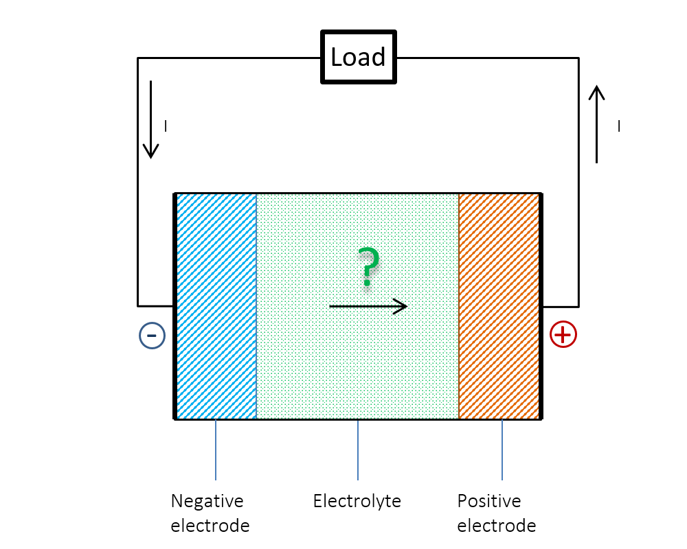
Figure 1. Does the current flow from a negative to a positive electric potential inside a battery?
The Double Layer Structure in Batteries
Let us look at what happens when we immerse a metal strip in an electrolyte; for example, a solution containing a dissolved salt. Depending on the type of metal and its structure, ions are adsorbed at the interface between the metal and the electrolyte. The first layer, next to the metal, usually consists of solvent molecules, but some ions that do not have a solvent sheath around them may also be contact adsorbed. Note that in this case, negative ions are contact adsorbed on negatively charged surfaces. This layer of solvent molecules and contact adsorbed ions is denoted by the inner Helmholtz plane (IHP); see Figure 2. Solvated ions of opposite charge to the metal surface may form an additional outer layer denoted by the outer Helmholtz plane (OHP).
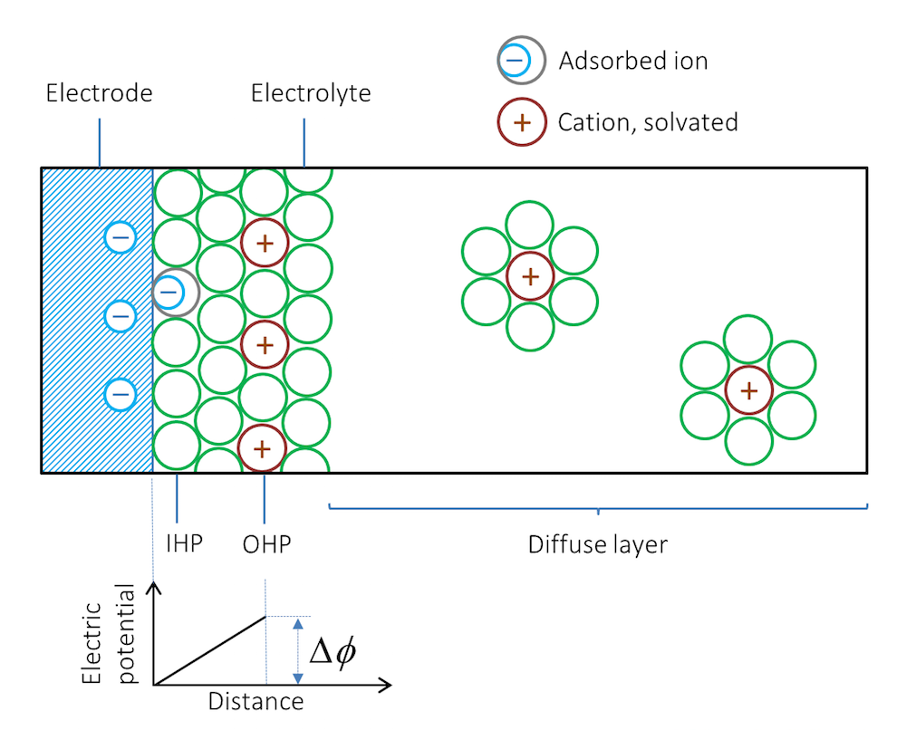
Figure 2. Schematic representation of the double layer. The green circles represent solvent molecules, which are everywhere to the right of the double layer but are drawn only around the solvated ions.
The metal surface and the layers of ions form the charged double layer. The potential difference across the charge double layer, ΔΦ, is created without any net flow of current.
Different metals have different affinities to keep electrons and, consequently, to attract ions of different charge. This also means that the potential across the charge double layer, in the absence of a current, is different for different metals in the same electrolyte.
If we immerse two metal strips made of two different metals in the same electrolyte and measure the potential with a high-impedance voltmeter to avoid any flow of current, we get a potential difference between the two strips. The schematic potential profile across the metal strips, the charge double layers (DL), and the electrolyte between the metal strips are shown by Figure 3. The high-impedance voltmeter is represented by a circle here.
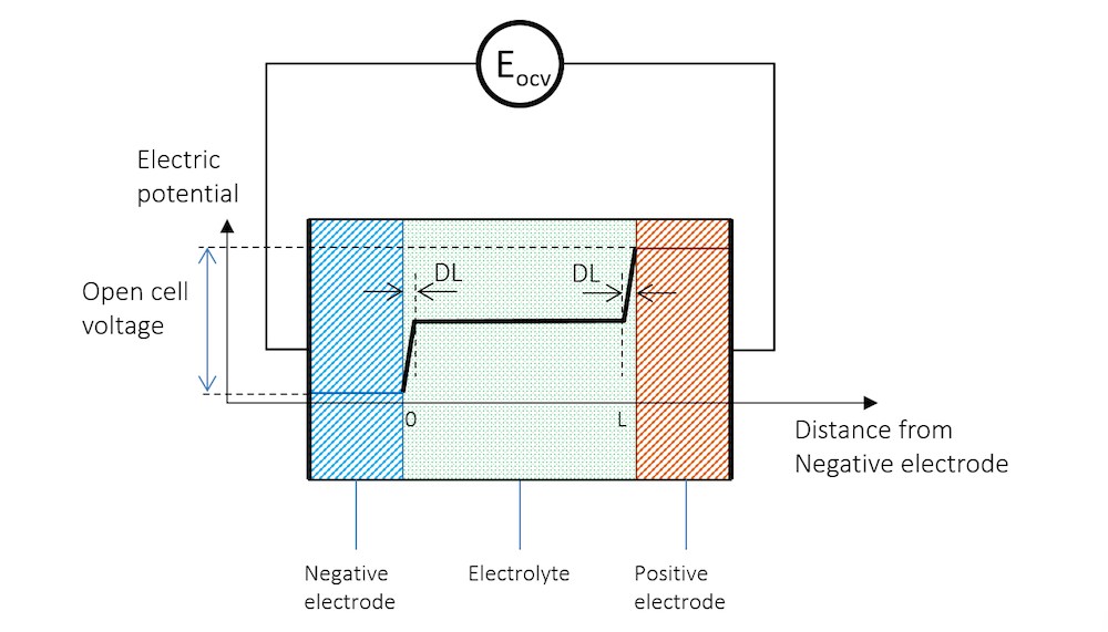
Figure 3. The electric potential profile across the negative electrode, the electrolyte, and the positive electrode connected to a high-impedance voltmeter to measure the open cell voltage (OCV).
The two metal strips now form the electrodes in our little battery. The more noble metal gets a positive potential, while the less noble metal strip gets a negative potential.
In Figure 3, the potential difference between the two electrodes is the exact amount required to keep the current from flowing in the system. The cell voltage in the absence of a net current, at equilibrium, is called the open cell voltage (OCV), denoted EOCV in Figure 3.
One example of such a battery is a battery made of a zinc metal strip, the less noble metal, and a copper strip, the more noble metal. The anodic reaction is zinc dissolution, while the cathodic reaction is the reduction of protons to hydrogen. It is possible to build such a battery by simply sticking the two metal strips into an orange, as shown in this tutorial model. The orange juice serves as the electrolyte.
Note that it is almost impossible to measure the equilibrium potential of an electrode. The reason is that as soon as we stick a measuring electrode into the electrolyte to measure the potential of another electrode, we get a charged double layer at the measuring electrode. Electrode potentials are therefore always measured against reference electrodes connected over a high-impedance voltmeter. The high impedance warrants that the measuring electrode is not subjected to any currents, which would change its potential.
The presence of the reference electrode is shown in Figure 4. The electrode potential at zero net current measured against a reference electrode is usually called the equilibrium potential, denoted Ee,vs Ref in Figure 4. Note that the reference electrode and the high-impedance voltmeter in Figure 4 measure the equilibrium potential of the negative electrode.
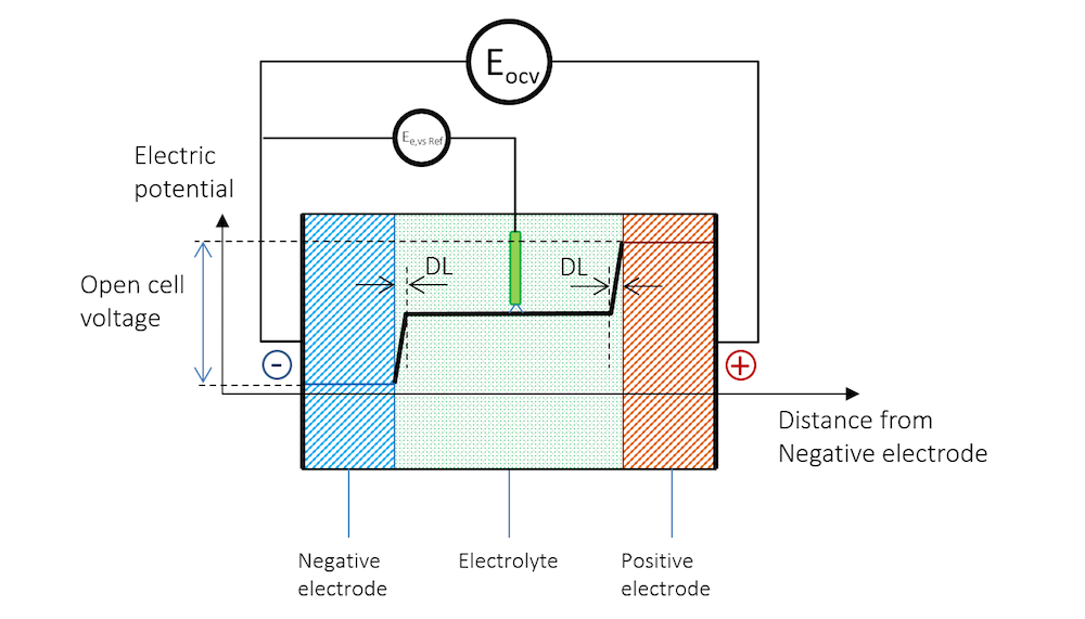
Figure 4. The reference electrode immersed in the electrolyte also gets a double layer on its surface, creating a contribution to the measured electrode potential.
Electric Potential During Discharge
We can now connect the two metal strip electrodes over a load in the external circuit; see Figure 5. Here, we assume that the current collectors and current feeders are able to perfectly distribute the current uniformly over the height of the electrodes. The electric potential is therefore also constant along the height of the battery electrodes and only varies along the thickness of the cell (the distance from the negative electrode).
By connecting the two electrodes over the load, we increase the potential at the negative electrode, decreasing the potential difference over the double layer. The more positive potential forces metal cations to be discharged to the electrolyte, releasing electrons to the outer circuit in an anodic reaction. In our little battery, the anodic reaction can be represented by:
At the positive electrode, the potential becomes less positive, attracting more positively charged ions that may be able to receive the electrons discharged in the cathodic reaction. Also, in this case, the total potential difference over the double layer decreases. In our battery, the cathodic reaction at a noble metal strip may be hydrogen evolution, which in its first step, may involve forming adsorbed hydrogen atoms:
Figure 5 schematically explains the change in potential between the OCV and the discharge and why the cell voltage of a battery decreases during discharge.
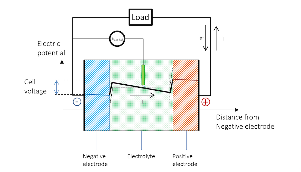
Figure 5. The potential across the battery during discharge. Note that there is a slope in the potential in the metal strips (blue and red lines) due to Ohmic drop. Note that in metals, the current is conducted by electrons, but by definition, in the opposite direction to the electric current. In other materials, charge carriers can be negative or positive. By convention, the current is always assumed to flow in the direction of positive charge, disregarding the material and mechanism for its conduction.
The reference electrode keeps its potential relative to the solution even during discharge, since there is no current flowing over it; i.e., the reference electrode is not polarized. It can therefore be used to separately measure the polarization of the two metal strip electrodes. In such a measurement, we also get the Ohmic losses along the thickness in the metal strips. These losses can be seen in the slight slope in the blue and red lines, and half of the Ohmic losses in the electrolyte, if the reference electrode is placed in the middle.
Figure 5 shows that the flow of current in the metal and in the electrolyte outside of the charged double layer can be purely Ohmic, although diffusion may contribute in many battery electrolytes. The current does flow from a positive to a negative potential outside of the double layer.
When modeling batteries and other electrochemical cells, the potential profile across the double layer is confined to a very thin region in the nanometer scale, compared to the electrodes and the electrolyte, which usually are in the millimeter scale. For this reason, in mathematical modeling, the double layer is treated as a discontinuity. The potential in the electrolyte is modeled with one dependent variable, usually denoted Φl, and the potential in the metal electrode is modeled with a second dependent variable, usually denoted Φs. The potential difference across the double layer is then defined as ΔΦ = Φs – Φl.
Charge Transfer Reaction, Charge Transfer Current, and Overpotential
The difference between the potential over the charged double layer in the absence of a current and in the presence of a current is called the overpotential. Again, since the charge double layer can only be measured relative to a reference electrode, the overpotential, η, is also measured relative to a reference electrode.
The overpotential is able to change the activation energy for the charge transfer reaction; i.e., the anodic oxidation and cathodic reduction reactions. This is visualized by Figure 6 for a metal Me that is oxidized anodically to Me+. The x-axis in the activation energy plot is the reaction coordinate for the redox reaction of the negative electrode. The plot correlates the free energy with the potential difference in the double layer, ΔΦ.

Figure 6. The activation energy for the charge transfer reaction is changed with the potential difference in the double layer, accelerating or decelerating the charge transfer reaction.
The anodic oxidation may be accelerated by increasing the potential of the negative electrode, thus somewhat decreasing the (negative) potential difference across the double layer. In the graph, the electric potential changes the free energy of the charged species. The charge transfer reaction thus “takes” electrons from the metal strip that acts as the anode, and delivers metal ions into the electrolyte. The electrons flow in the external circuit over the load to the positive electrode; see Figure 5. The ions in the electrolyte migrate in the electric field, transporting the current in the electrolyte to the positive electrode, which is also shown in Figure 5.
The process shown in Figure 5 and Figure 6 can be represented in a plot that shows the charge transfer current density, ict, as a measure of the electrons transferred in the charge transfer reactions as a function of the potential. This is shown in Figure 7. The two curves show the charge transfer current density over the interface between the electrolyte and the metal as a function of potential. The curve for the negative electrode is blue and the curve for the positive electrode is red.
During discharge, the negative electrode gets an anodic current density of a value ict,a at an anodic overpotential, ηa; i.e., the electrode is polarized positively. This is also consistent with Figure 5 above. The potential difference ΔΦ is a small negative value, while the same difference at equilibrium is a larger negative value, resulting in a positive overpotential. An anodic current is, by definition, a positive current.
The positive electrode is polarized negatively, which, by definition, gives a negative cathodic current. In this case, the current has a value of ict,c with an opposite sign but of the same absolute value as the anodic current density, if the metal strips have the same area (Kirchhoff number). The corresponding cathodic overpotential is ηc. In the absence of mass transport limitations, the Butler-Volmer equation can describe the red and blue curves in Figure 7.
Like Figure 5, Figure 7 also explains why the cell voltage, Ecell, decreases at discharge compared to the open cell voltage in Figure 3. It may actually decrease a little more than this figure shows, since some of the potential is also lost in Ohmic losses, which are not included in the plot.
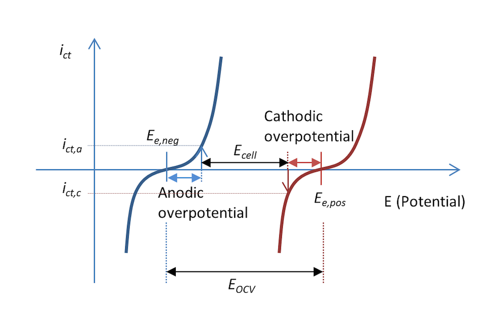
Figure 7. The charge transfer current density as a function of the electrode potential for the negative and positive electrodes in our little metal-strip battery during discharge. In this case, the discharge current density is abs(ict,c) = ict,a.
Recharging the Battery
Assume now that we would like to recharge the metal-strip battery. This requires reversing the charge transfer reactions, so that a cathodic charge transfer reaction occurs at the negative electrode and an anodic charge transfer reaction occurs at the positive electrode.
Figure 8 shows that in order for recharging to take place, the negative electrode has to be made more negative, which increases the potential over the charge double layer. This corresponds to a net reduction reaction, as shown in Figure 6. The negative electrode now becomes the cathode with a negative charge transfer current density. The cathodic reduction reaction may be the following:
The positive electrode has to be made more positive. This also increases the potential over the charged double layer. This corresponds to a net oxidation reaction for our battery. The positive electrode is now the anode, with a positive charge transfer current density. In an aqueous electrolyte, and for a more “noble” metal strip, this could typically be the oxidation of hydroxide ions. In a first step, this oxidation may involve the adsorption of hydroxyl at the anode surface:
In a second step, this would generate water and oxygen. For more noble metals, an even higher potential would be required in order to discharge metal ions into the solution. Therefore, the typical reaction in water electrolytes is to first oxidize hydroxide ions, or to split water, and form oxygen.
Figure 8 explains why recharging a battery requires a higher voltage than the open cell voltage.
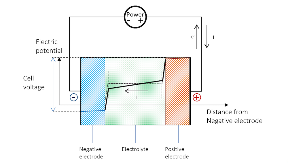
Figure 8. The potential across the battery during recharge. Note that here, like during discharge, there is a slope in the potential in the metal strips (blue and red lines) due to Ohmic drop.
The current density due to the charge transfer reactions at the two metal electrode surfaces is shown in Figure 9. The negative electrode is polarized negatively, resulting in a cathodic current, which, by definition, is negative. The positive electrode is made even more positive; i.e., it is polarized positively and an anodic current is obtained, which is positive. The figure also explains why the voltage over a battery has to be larger than the open cell voltage during recharge in order to drive the required anodic and cathodic currents .
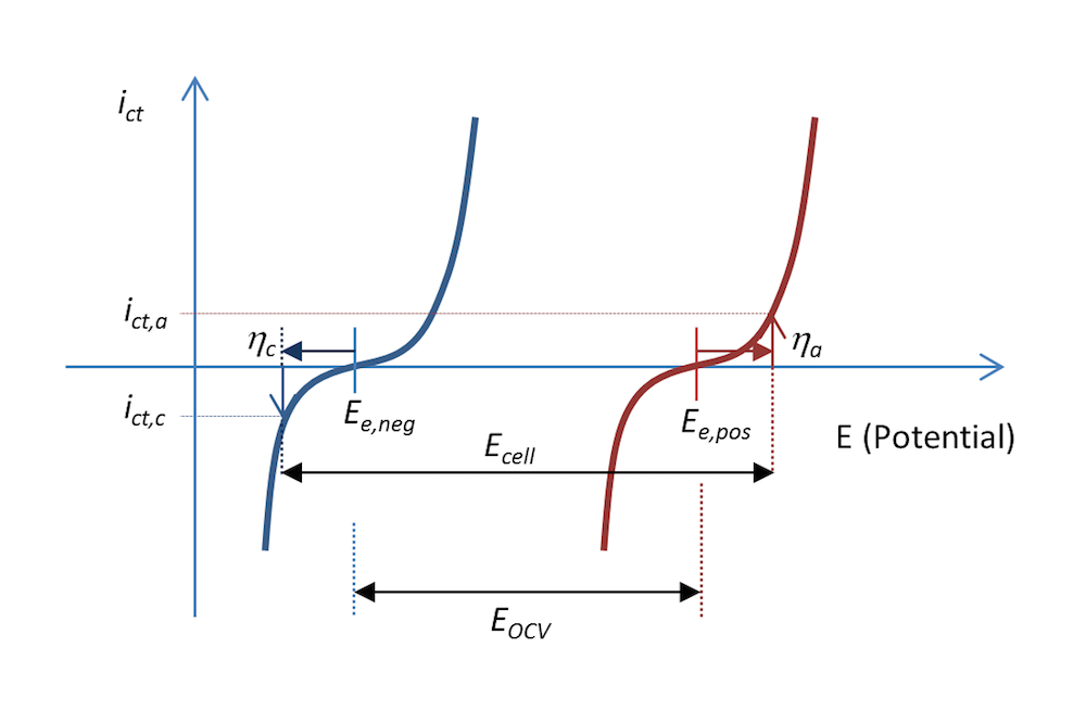
Figure 9. The charge transfer current density as a function of the electrode potential for the negative and positive electrodes in our little metal-strip battery during recharge, at a current density of ict.
Porous Electrodes
Most batteries use porous electrodes, not solid metal strips, as electrodes. This provides a much larger surface area for the electrochemical reactions, and therefore “compacts” the battery into a unit that weighs less for the electrical output it can provide. In these batteries, the pores in the electrodes contain electrolytes, denoted as pore electrolytes. The charged double layers are formed all around the pore walls that are in contact with the pore electrolytes, thus increasing the surface area and decreasing the local charge transfer current density and also the overpotential losses during discharge and recharge.
Figure 10 shows the potential distribution in a battery with porous electrodes at open cell voltage. The electrolyte potential is defined both in the free electrolyte and in the pore electrolyte.
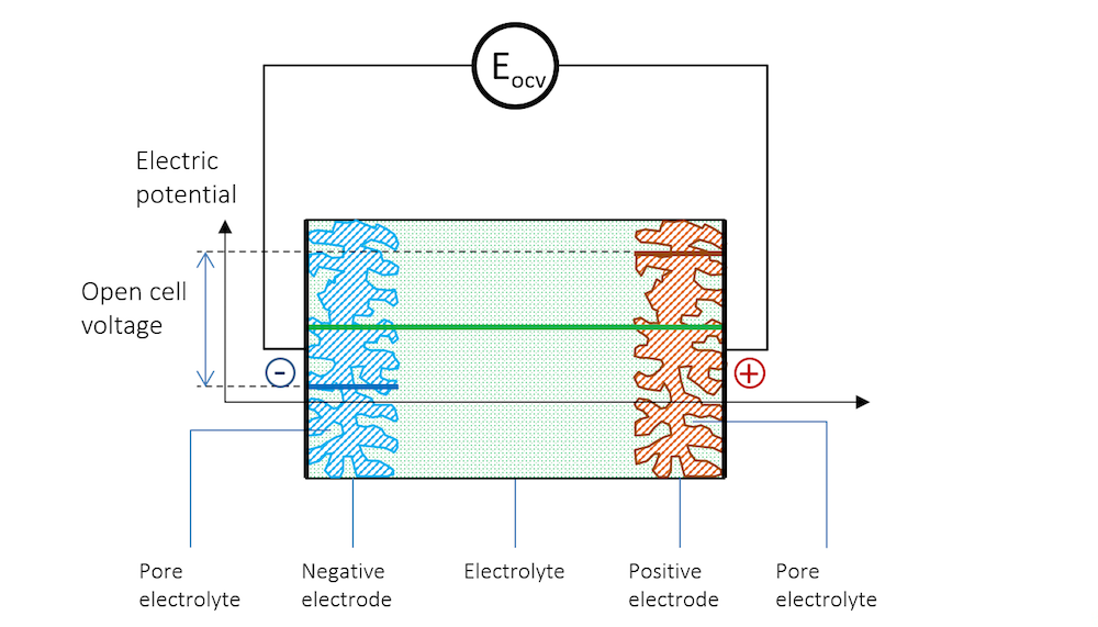
Figure 10. Potential profile in the electrolyte, pore electrolyte, and in the porous metal in a battery with porous electrodes.
As we discharge the battery, current flows from the electrode material into the pore electrolyte at the negative electrode. This means that the pure Ohmic current density in the pore electrolyte increases as we go from the current feeder of the negative porous electrode to the edge facing the free electrolyte between the electrodes, from left to right along the x-axis, as shown in Figure 11.
Since the average current density is not constant as a function of x, the potential profile in the pore electrolyte is not a line with constant slope. The curvature in the potential profile is shown by Figure 11. In the negative electrode’s pore electrolyte, the slope of the electrolyte potential (green) increases with x. The slope in potential in the porous metal (blue curve) decreases with x, since the current transfers to the electrolyte in the charge transfer reaction along the x-axis.
At the positive electrode, the opposite process takes place. The slope at the edge facing the free electrolyte is at its maximum for the potential in the pore electrolyte (green) and decreases with x, since current is transferred from the pore electrolyte to the porous metal at the positive electrode. The slope in potential in the porous metal (red) increases with x as more current is transferred from the pore electrolyte. At the position of the current collector, all current flows in the metal.
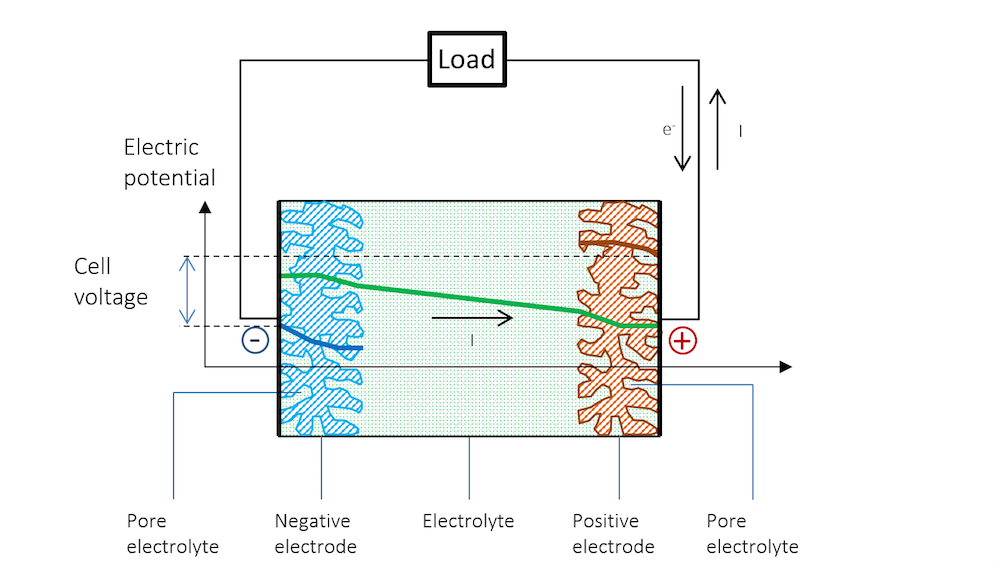
Figure 11. Potential profile in a battery with porous electrodes during discharge.
Concluding Remarks on Electric Current Flow Inside Batteries
Although this discussion may sound trivial, understanding the above principles is probably one of the most important requirements for a conceptual understanding of electrochemistry. It takes some reading and hands-on modeling and simulation work to acquire this understanding. No wonder my teacher at school had problems explaining this concept!
Additional Reading
- Orange Battery tutorial model
- 1D Isothermal Lithium-Ion Battery tutorial model
- J. O’M. Bockris and A. K. N. Reddy, Modern Electrochemistry Volume 2, Springer-Verlag, 1970.
- J. Newman and K. E. Thomas-Alyea, Electrochemical Systems 3rd Edition, Wiley, 2004.
Editor’s note, 2/13/2020: Per reader requests, we have uploaded model files to go along with this blog post to the Application Gallery entry “Potential Profile in Batteries and Electrochemical Cells“.


Comments (10)
Xiaoguang Yin
November 19, 2018Thanks for this very inspiring post, it solves my question since high school.
cory skinner
January 30, 2020Thanks so much! It’s amazing how much inaccurate information is taught on this subject. However, as you said, It’s a difficult concept to understand never mind teach!
Ed Fontes
February 13, 2020 COMSOL EmployeeThank you for the kind words Cory!
Steve Sybesma
April 12, 2020For every person like you who greatly confuses the public about how electric current works by claiming it runs from positive to negative, there are posts like this which depict the only actual movement of subatomic particles in a circuit, which is ELECTRON movement:
http://www.qrg.northwestern.edu/projects/vss/docs/power/2-how-do-batteries-work.html
Conventional current is what you’re speaking of and was a sideline topic when I was learning about electricity 40 years ago. Basically it can be seen as ‘hole’ flow. The progressive displacement of ‘slots’ where electrons used to be travels backward from the electron flow just like one light in a loop of lights which turns off moves in the opposite direction of the light turning on.
Protons do not move, therefore what causes electrical current? The displacement and movement of electrons which happens when a circuit is attached to a power source. The negative end having an excess of electrons and the positive end having a shortage of electrons causes the electrical potential (voltage) which causes the electrons to move. There is no surplus of isolated protons at either end of the power supply as there are electrons.
Benjamin Franklin made the mistake of saying current moved from positive to negative and was corrected in 1897 by J.J. Thompson who discovered electrons and what was really going on in a circuit, in that the only actual movement was electrons going from negative to positive.
You overstress conventional current while not even acknowledging electron current. For a beginner who doesn’t know the difference between either one, it’s a disservice on your part.
Brianne Christopher
April 13, 2020Hi Steve,
The direction of the electron current relative to the conventional electric current is shown in figures 5, 8, and 11. But we have added a clarifying comment in figure 5.
Patrick Campbell
March 16, 2022I think you are treating the author a bit unfairly. It is important to realize that electrons are not always the charge carriers of a system. In metal conductors, it is indeed electrons that flow. In complex solutions, it is both anions and cations that flow and move. This was quite clearly shown by the author in Figure 2, where the migration of positive ions is needed in order to form the Outer Helmholtz Plane on a negatively charged electrode. Sometimes, there isn’t even a physical, moving charge carrier needed (see Displacement Current in capacitors)!
My props to the author of this article. I’d love to have even more access to articles like this that go more in depth, such as highlighting the other nuances in the system such as the different potential types (electrochemical potential vs electric potential), or how the modeling of the different double layer effects (on both the micro and macro scale) in COMSOL pans out.
Steve Sybesma
April 12, 2020Incidentally you say Ohm’s Law states current goes from positive to negative. Only problem with that is Georg Ohm was alive about the same time as Benjamin Franklin and J.J. Thomson confirmed both of them wrong in that case. Maybe update your science books?
Maricruz Bautista Ramírez
May 5, 2021Thanks for this information, It is very useful in my thesis work!
bob sepassi
December 17, 2021this is an amazing article describing the workings of a battery, down to ion level.
but the choice of conventional current direction maybe does not fit this superb paper.
it would be much better understandable for readers like me to follow electron flow direction.
Hokyung Park
April 17, 2023Wonderful!
I don’t understand why this kind of subject would not be discussed as much as expected.
Most of people, even the experts, pretend to know without any doubt.