

When exciting or terminating an RF device with a specific impedance value on a location where the transverse electromagnetic (TEM) mode is expected, the Lumped Port feature is useful. Available in the RF Module, an add-on to the COMSOL Multiphysics® software, the Lumped Port feature is a boundary condition with many different variations and application areas. Let’s go over a few of them here.
A Brief Introduction to Lumped Ports
Lumped ports are used to excite or terminate passive circuits and antennas, as well as to compute frequency responses of devices, such as impedance matching and insertion loss in terms of S-parameters.
There are a couple of conditions to obtain physically valid S-parameters while using lumped ports. In order to generate S-parameters, there must be a single excited lumped port. The conventional S-parameter definition works only with a real characteristic impedance. The calculated S-parameter is not physical when a complex port reference impedance is used. In the case of an UHF RFID tag, for instance, the power wave reflection coefficient term needs to be studied for evaluating the matching properties of the device.
While lumped ports and port boundary conditions are well suited for wave electromagnetics problems, here, we focus on the applying lumped ports for each port type through several examples from the RF Module Application Library.
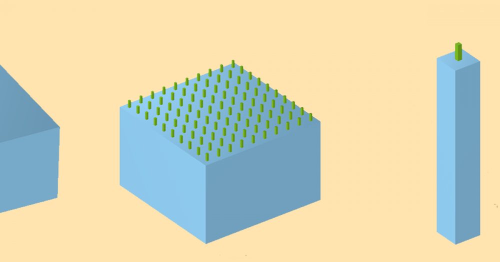
A monopole antenna array showing beam scanning capability. The model uses multiple lumped port excitations with arithmetic phase change. For phased array antenna applications, it is possible to excite multiple lumped ports with phase progression on each lumped port.
A Lumped Port feature can be applied on a tiny portion of a model, where the size of the lumped port boundary is small enough with respect to the operating wavelength. Thus, it is assumed that any phase variation in the small area is negligible. The use of this feature is restricted to the gap surface between two metallic (conductor) boundaries that supports the TEM mode.
Lumped ports are categorized by their geometric shape:
- Uniform
- Coaxial
- Multielement uniform
- User defined
Let’s go over a few examples…
Uniform Lumped Ports
Use a Uniform lumped port to excite or terminate a device through a small rectangular boundary. Several examples in the RF Module Application Library demonstrate the use of this type of lumped port.
Strip Antennas
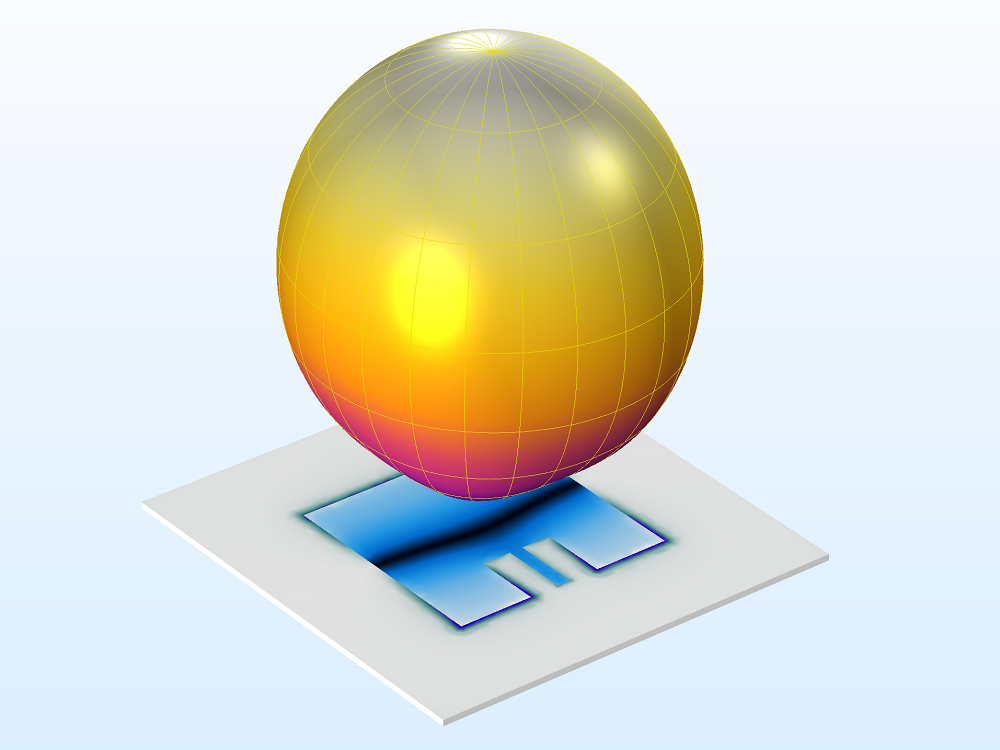
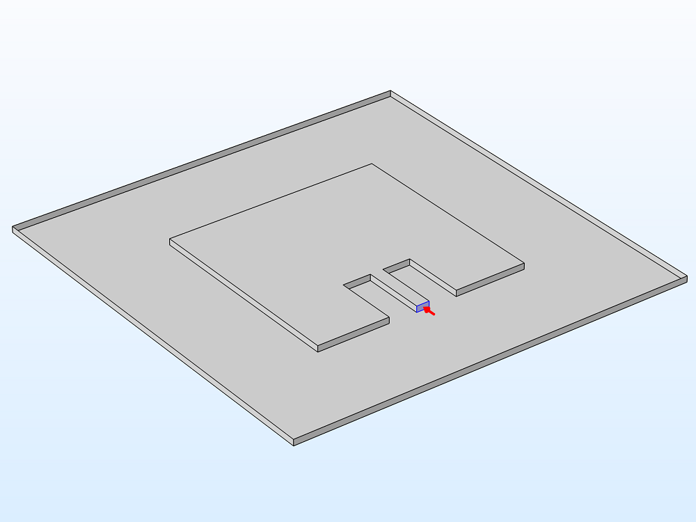
When exciting a strip antenna printed on a dielectric board to measure the input impedance and S-parameters, as well as to compute the radiation pattern with a far-field feature, use a lumped port on the gap between the two conductive strips.
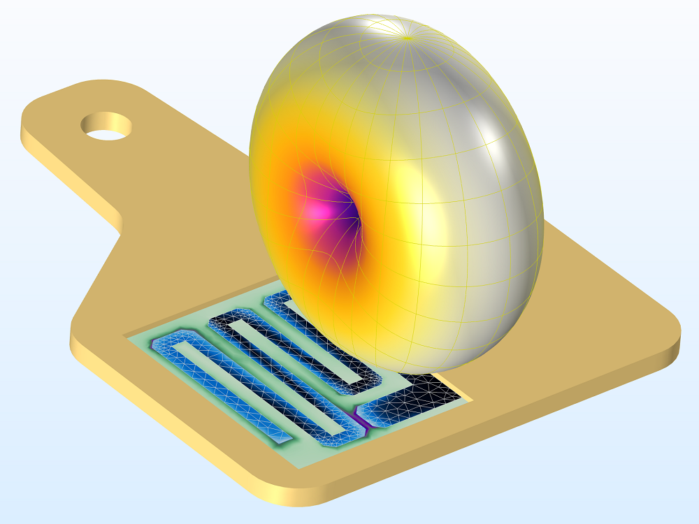
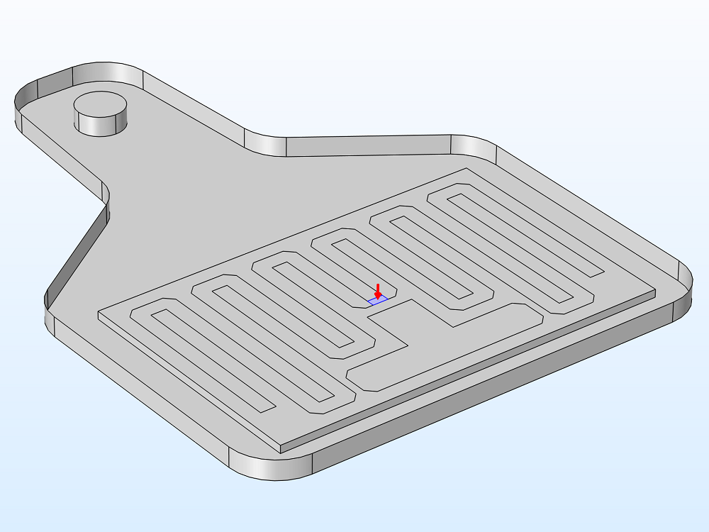
Left: A UHF RFID tag model. Right: The boundary selection of the uniform lumped port in the middle of a printed metallic strip.
Microstrip Circuits
When exciting and terminating a microstrip line circuit to compute S-parameters, you can add a lumped port on the gap between the end of the microstrip line and bottom ground plane. The fringing field around the microstrip line is ignored. If it is important to capture the fringing field, you can use a numeric port with the TEM option.
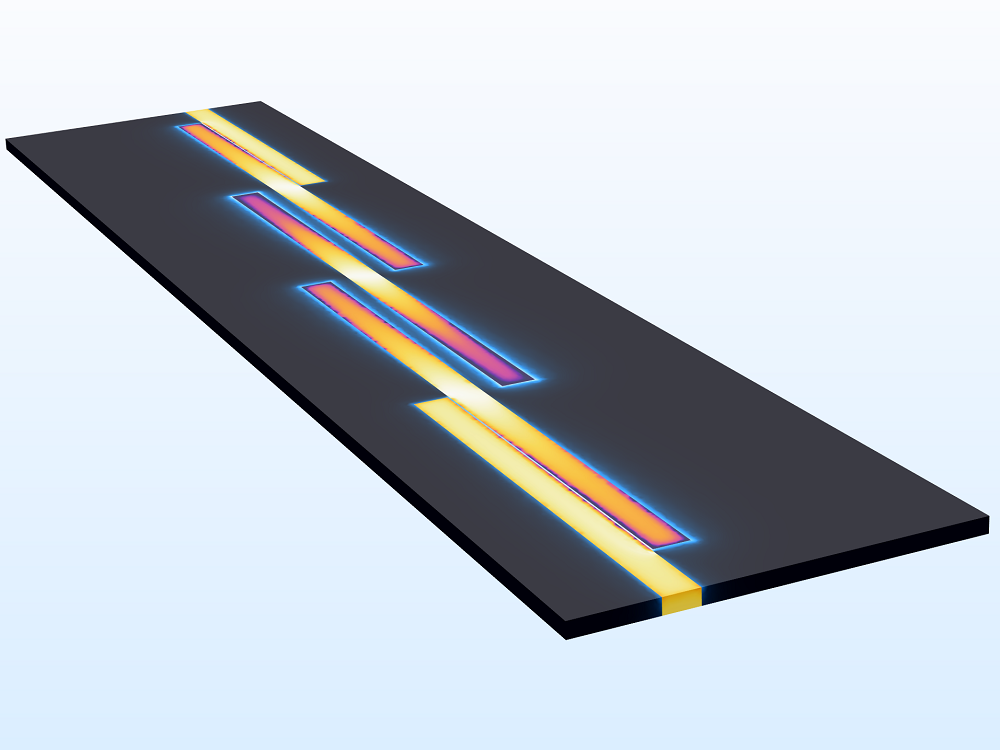
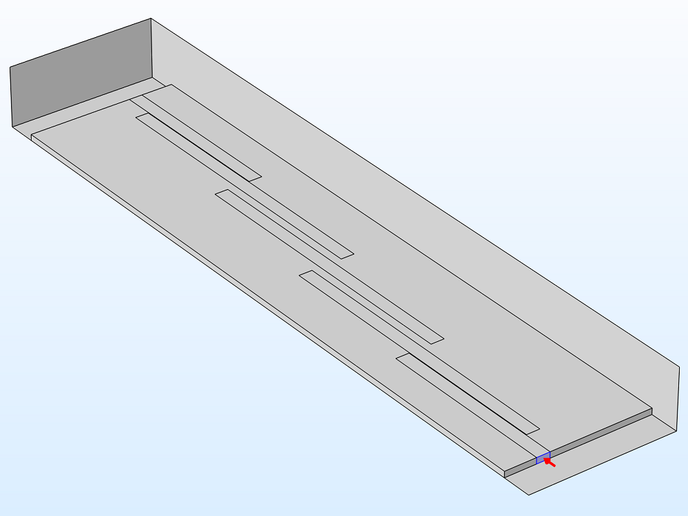
Left: A coupled line filter model. Right: The boundary selection of the uniform lumped port at the end of a microstrip line filter.
Slot Antennas
When exciting a slot antenna patterned on a dielectric substrate to compute the input impedance and S-parameters, as well as to study the radiation characteristics with a far-field feature, you can assign a lumped port across the slot connecting two edges of conductive planes.
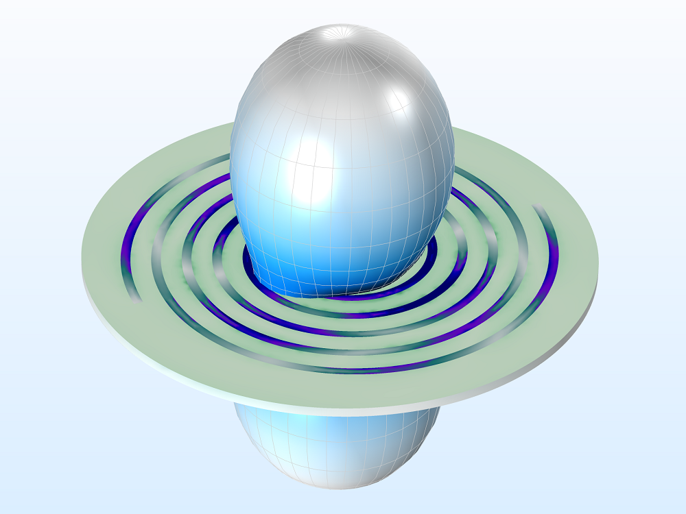
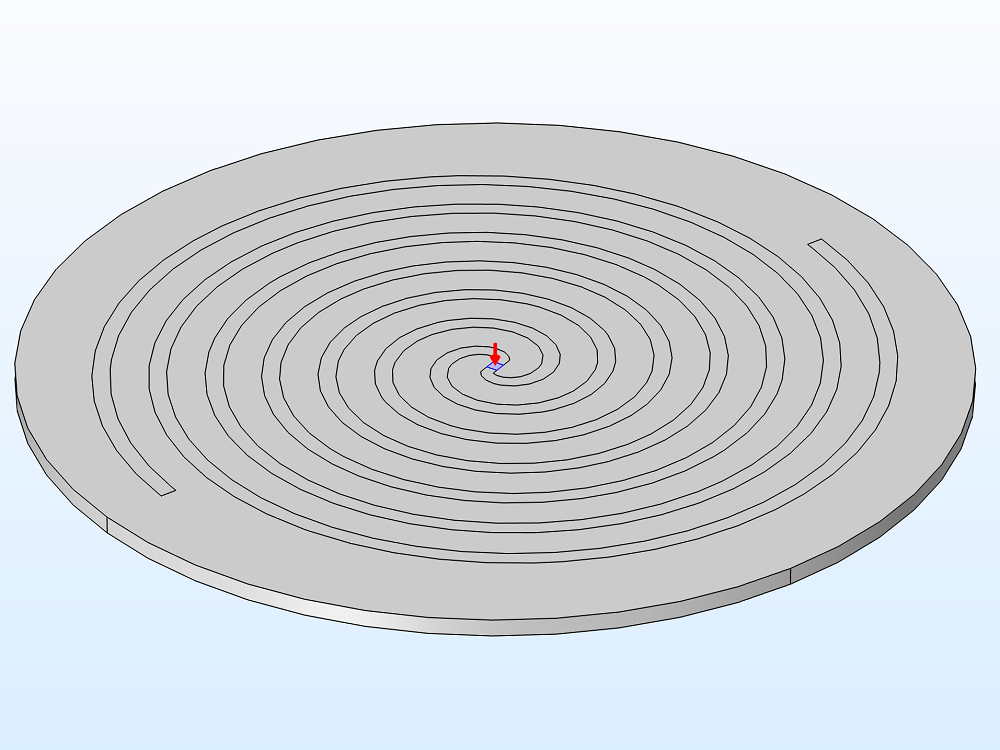
Left: A spiral slot antenna model. Right: The boundary selection of the uniform lumped port across a slot.
Microstrip Patch Antennas
To excite a microstrip patch antenna fed by a microstrip line to calculate the input impedance and S-parameters, as well as to compute the radiation pattern with a far-field feature, you can assign a lumped port on the gap between the end of the microstrip line and bottom ground plane.
Left: A microstrip line patch antenna model. Right: The boundary selection of the uniform lumped port at the end of a microstrip line.
Coaxial Lumped Ports
The Coaxial type of lumped port is appropriate for addressing coaxial cables and coaxial connectors, such as SMA and edge launch connectors.
SMA Connectors
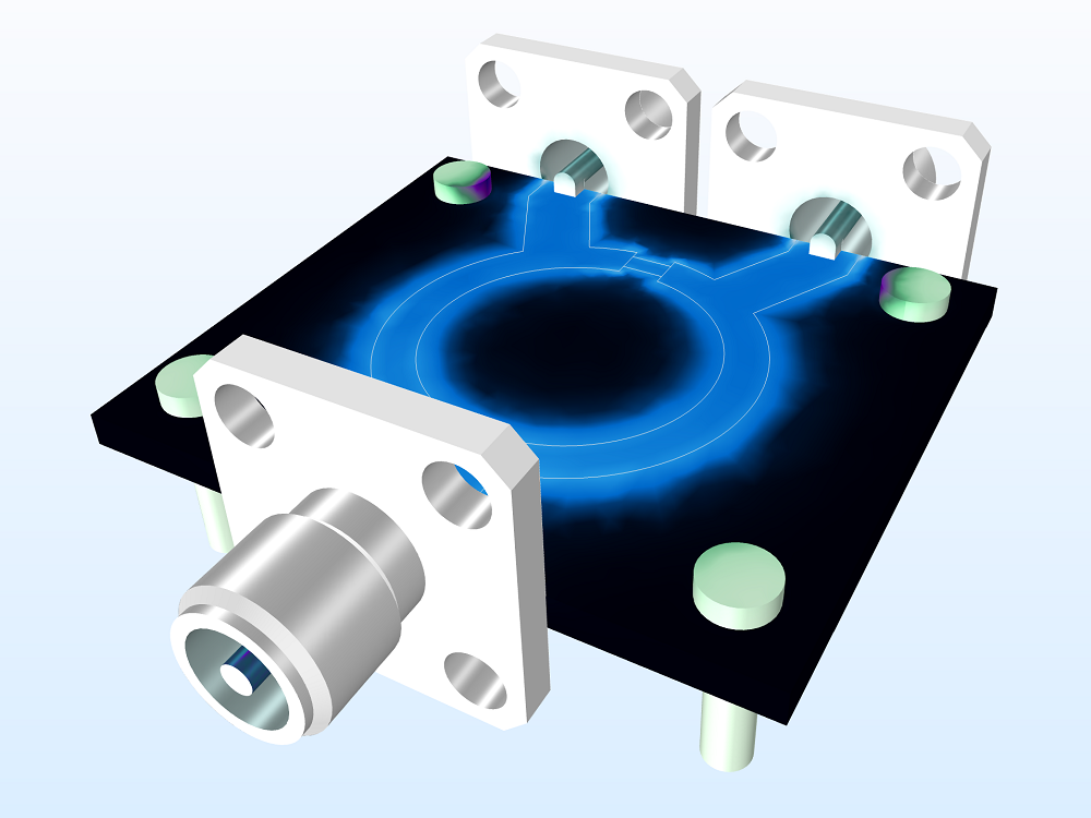
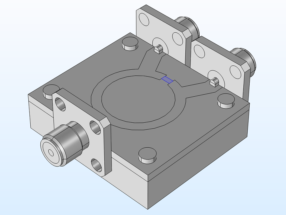
When exciting and terminating a coaxial connector to compute S-parameters and input impedance, assign a lumped port on the annular boundary between the center and outer conductor of an SMA connector.
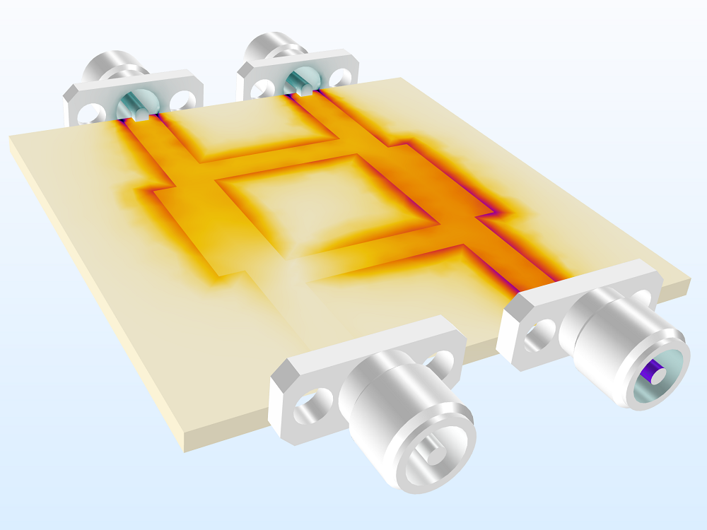
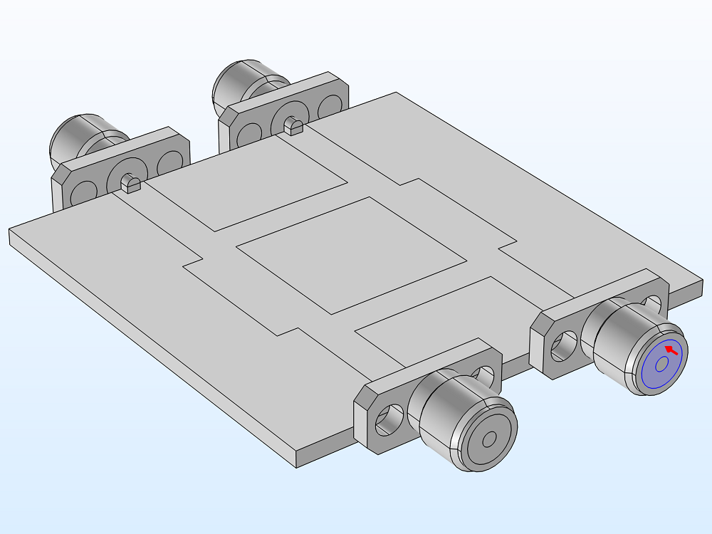
Left: A branch-line coupler model. Right: The boundary selection of the coaxial lumped port on an SMA connector.
Coaxial Cables
The end of a coaxial cable can be finished with a coaxial lumped port to compute S-parameters and input impedance. Just like the SMA connector case, you can use a lumped port on the annular boundary between the center and outer conductor of the cable.
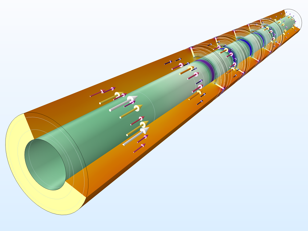
Left: A coaxial low-pass cable filter model. Right: The boundary selection of the coaxial lumped port in a 2D axisymmetric model.
Multielement Uniform Lumped Ports
To address the excitation and termination of a coplanar waveguide (CPW) or the common or differential mode on two parallel microstrip lines, use the Multielement Uniform type.
Coplanar Waveguides
When a coplanar waveguide (CPW) is excited or terminated using a single lumped port boundary, it requires a conductive air-bridge between the ground planes or common ground plane surrounding the center conductor. You can bypass this additional modeling work by choosing the Multielement Uniform lumped port. This port configures the CPW model with a pair of subfeatures called Uniform Elements. Each uniform element is assigned on the slot next to the left and right sides of the center conductor, respectively. It is valid only when the power is equally distributed on both slots.
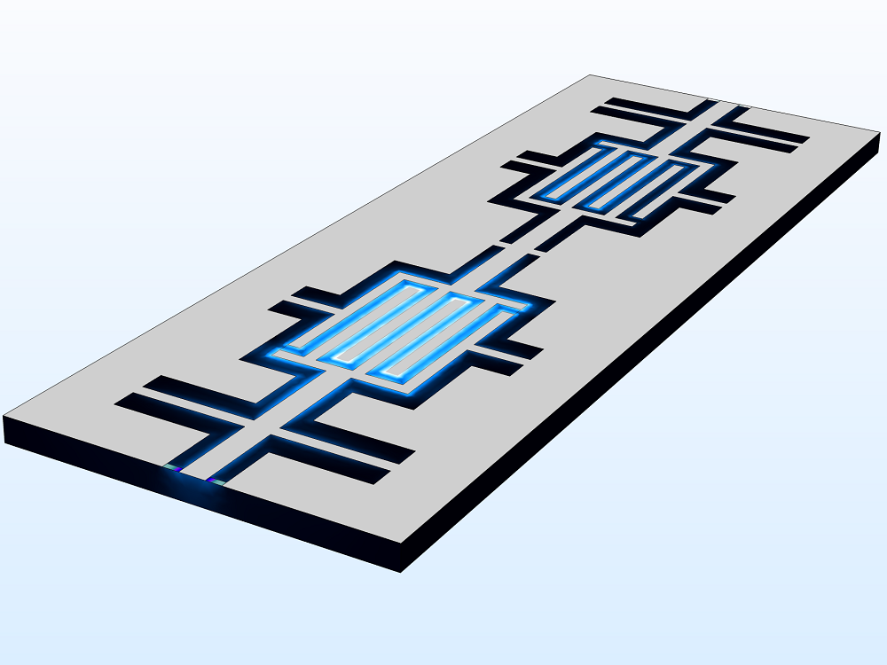
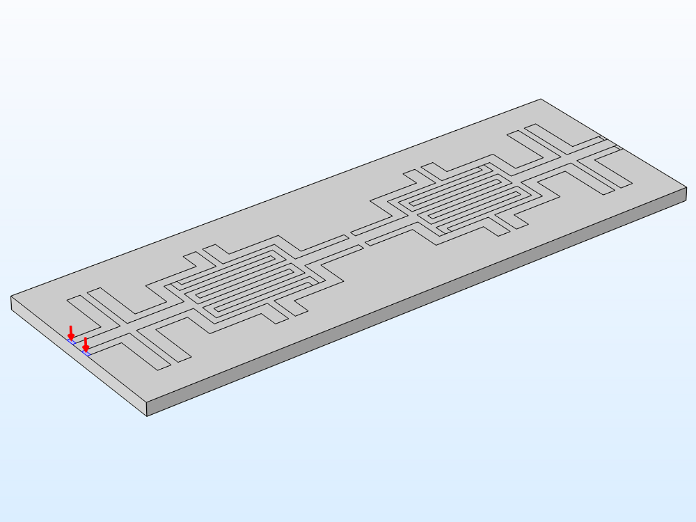
Left: A CPW bandpass filter model. Right: The boundary selection of the multielement uniform lumped port.
User-Defined Lumped Ports
If the shape of a lumped port boundary cannot be defined by a coaxial, multielement uniform, or uniform lumped port, then you can use the User Defined type, as long as the height and width of the lumped port boundary are constant and the polarization is definite.
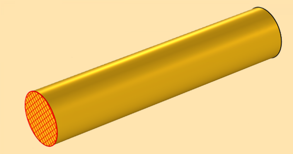
Excitation and Termination on a Curved Boundary
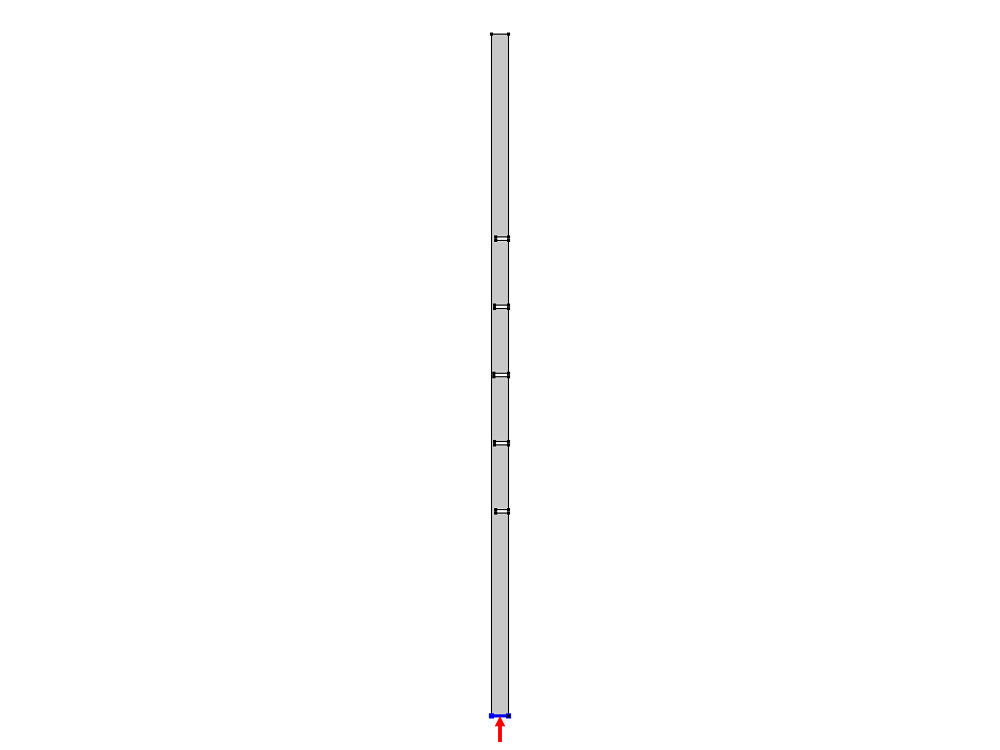
To assign a lumped port to a cylindrical structure, you should select a set of circumferential boundaries that lie between conducting boundaries. The lumped port is applicable on a small segment of a conductive cylindrical structure or a metallized via between a signal path (microstrip line) and a bottom ground plane.
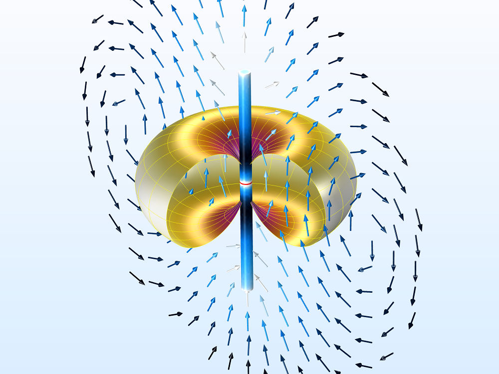
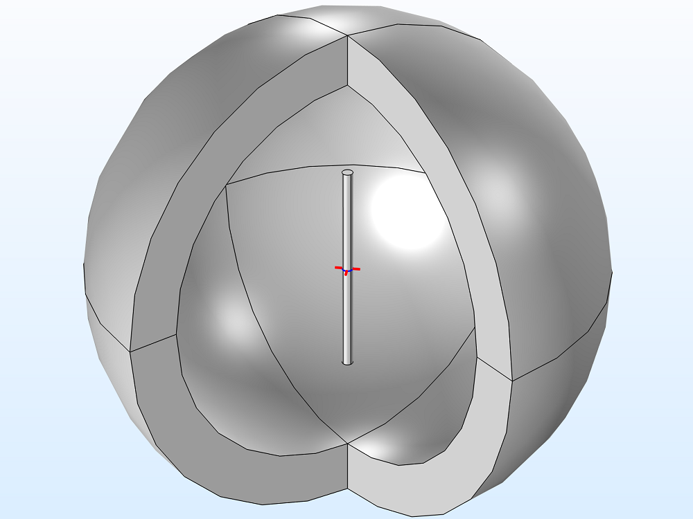
Left: A dipole antenna model. Right: The boundary selection of the user-defined lumped port in the middle of a cylindrical structure.
Resembling Lumped Ports with the Lumped Element Feature
The Lumped Element feature is a passive lumped port boundary condition that can be used to terminate a circuit and an antenna with a specified device type. This feature is not meant for exciting a circuit or an antenna as a source.
You can use a Lumped Element feature to describe the insertion of a capacitor, inductor, general impedance, or a simple combination of reactive devices between two conductive boundaries. While using a lumped port with a single-port excitation computes S-parameters, this feature does not generate S-parameters. The Lumped Element feature supports the same geometric shapes as the Lumped Port feature and it is configured as a device with a user-defined impedance value, capacitor, inductor, series LC (inductor-capacitor combination), parallel LC, series RLC (resistor-inductor-capacitor combination), or parallel RLC circuit.
Resistors
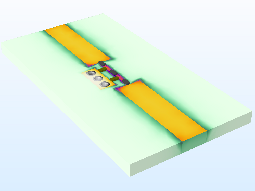
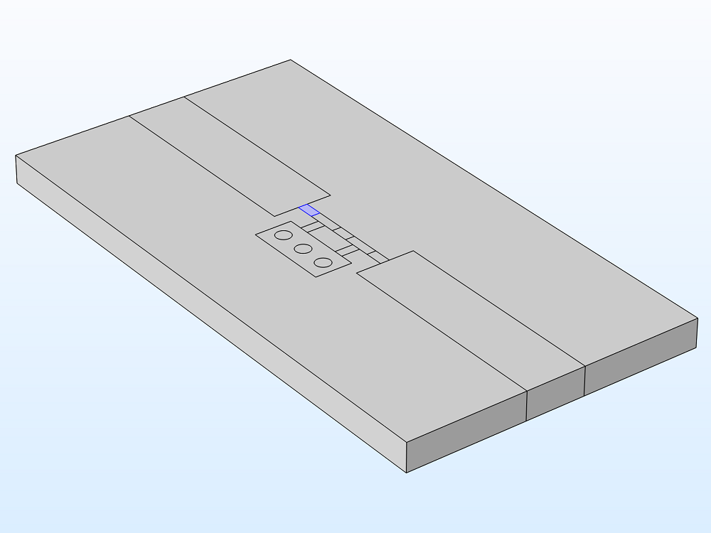
A surface mount device, such as a resistor, can be added in the middle of microstrip lines. Use a lumped element on the gap bridging the two conductive edges with a specified impedance value.
Left: A Wilkinson power divider model. Right: The boundary selection of the uniform resistor lumped element.
Capacitors and Inductors
Reactive surface mount devices, such as capacitors and inductors, are used to build low-frequency RF filters. Choose an appropriate lumped element device type and assign the lumped element on the boundary between the two microstrip line ends.
Left: A lumped element filter model. Right: The boundary selection of the uniform capacitor lumped element.
Next Steps
Learn about more specialized features available for your RF and microwave modeling:
The Lumped Port feature is not limited to the examples mentioned in this blog post. You can find many useful RF tutorial models in the Application Gallery with easy-to-follow, step-by-step instructions.

Comments (4)
Mohammed Al-Daloo
December 8, 2019Thanks for this a great explanation for Lumped Ports. So, could I terminated a microstrip line with a capacitive load, but what does “Choose an appropriate lumped element device type and assign the lumped element on the boundary between the two microstrip line ends.” mean? could you please explain it more, or give me a link illustrate this step, please.
Jiyoun Munn
December 17, 2019 COMSOL EmployeeYou can select the “lumped element device” type from the settings window of a lumped element feature. That can be User defined (the default), Inductor, Capacitor, Parallel LC, Series LC, Parallel RLC, or Series RLC. So, you may specify a complex value of impedance, inductance, capacitance, or a combination of these.
See these models:
https://www.comsol.com/model/mri-birdcage-coil-16991
https://www.comsol.com/model/a-low-pass-and-band-pass-filter-using-lumped-elements-15675
Amare Abay
September 24, 2020Thanks Jiyoun for this a great explanation, could you help me how to plot Signal to Noise (SNR) with the RF Module.
Thank You.
Peter Frank
May 16, 2022Is there a guideline on how far a lumped port should be from a boundary? For example, looking at the Coupled Line Filter example, why is a distance of 2.5 mm chosen? Is there a rule of thumb based on substrate thickness, line width, frequency, etc?